A Visio user recently asked if it is possible to assign shapes to layers from a list. In his case, he has an Excel table which he has exported shapes and their text using Visio’s Shape Reports feature, to which he has added a column named Layer, and he wants to assign the shapes to these layers. In this article, I demonstrate how this can be done.
I decided to use my MVP Session Wheel diagram ( see http://blog.bvisual.net/2012/06/29/mvp-sessions-wheel/ ) for this example because it already has some layers assigned.
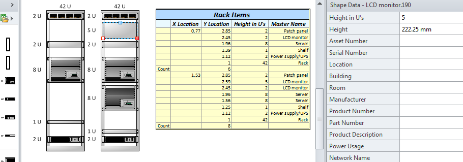
I created a new Shape Report called Presenter Shapes, where I filtered all shapes on the current page to those where the Presenter Shape Data row exists, and the Presenter actually has a value:

[Read more…] about Assigning Shape Layers from a List in Visio