I got a surprise in one of my projects when I counted the shapes glued together using the Shape.GluedShapes(…) method … the sum of the filtered glued shapes just didn’t add up to the unfiltered count. So, I thought I should check the Shape.ConnectedShapes(…) method too … and there is a scenario where that has a similar result.
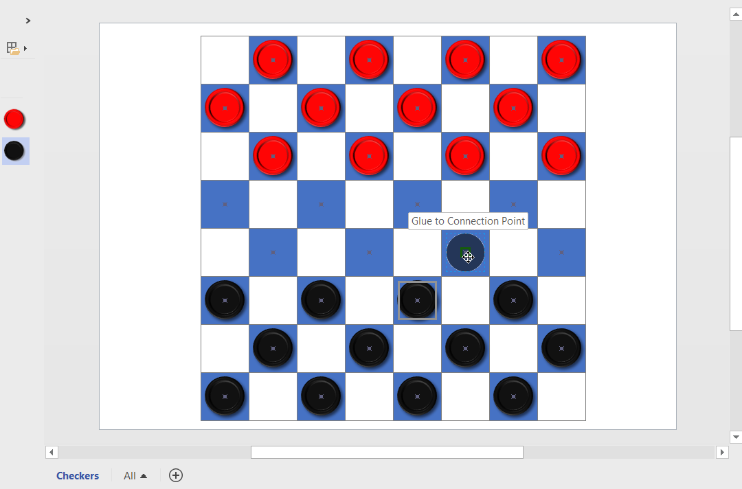
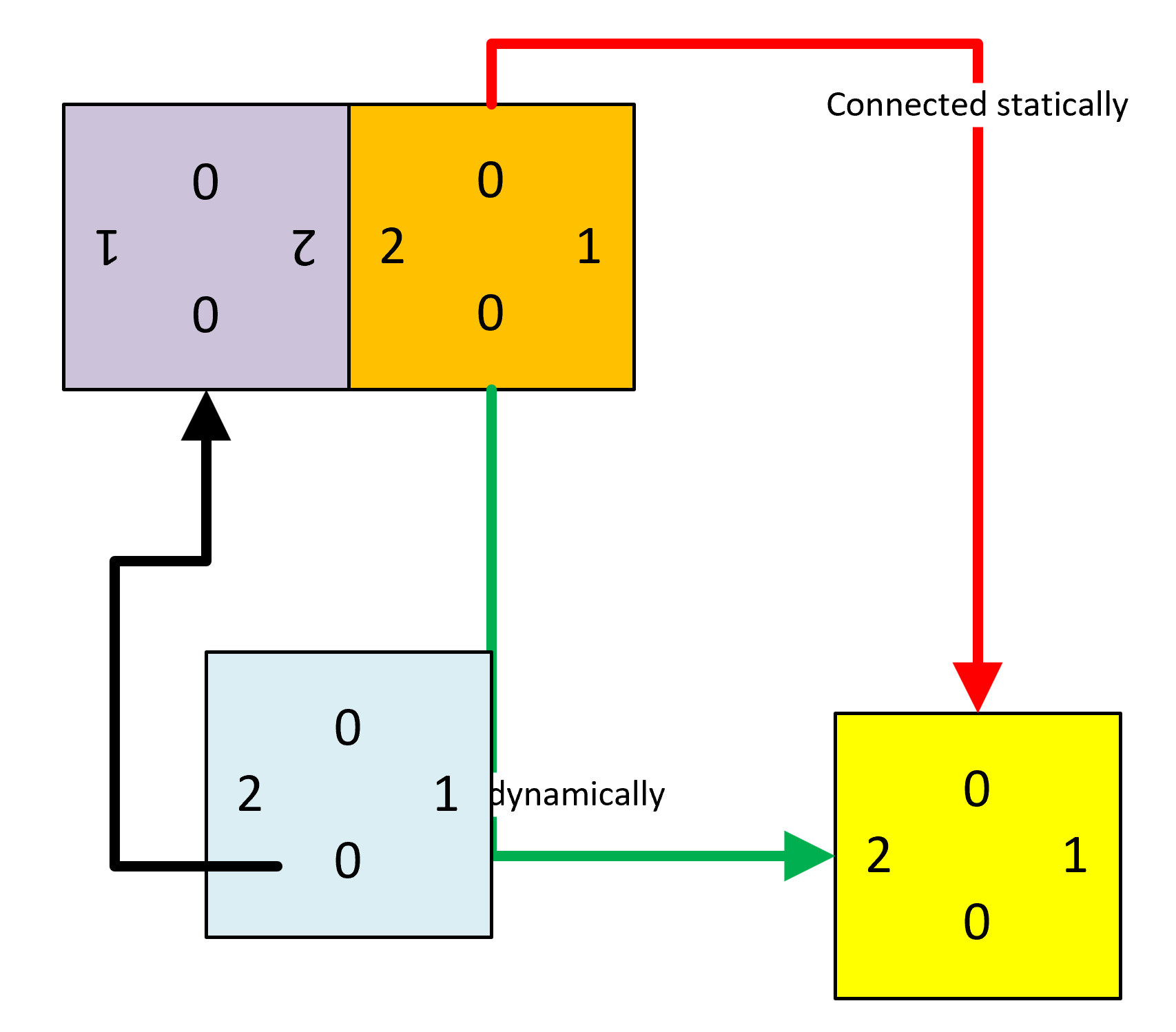
In the following diagram, I have different coloured squares with connection points of different types at the centre of each edge (as denoted by the connection type numbers), and one under a control point in the bottom left corner. I have glued the ends of coloured connector lines, statically (Red and Black) and dynamically (Green), and glued the Purple Square directly to the Orange Square. The Blue Square shape is glued to a connection point on the green dynamic connector.
I then ran some code to get the count of glued and connected shapes … and noticed some apparent discrepancies…
[Read more…] about Counting glued and connected shapes in Visio