I was recently asked to represent the values of Key Performance Indicators (KPIs) in Visio. Great, I thought, this is just what Visio’s Data Graphic Icon Sets are for! Only trouble was, that there were six possible values for the KPI, but all the example Icon Sets have a maximum of five icons in them. So, I had to come up with a way of displaying six icons …
In the following example, I have defined a Shape Data row with a Fixed List type that can have a value from the list “3;2;1;-1;-2;-3”
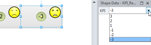
I applied the Faces Icon Set, and set icons for each value, except for –1:
[Read more…] about How to have six icons in a Visio Data Graphic Icon Set