I have created many Visio solutions over the past 25 years and used a number of methods of creating an installation that includes Visio templates and stencils. I have just wasted many hours trying to debug an installation created with Advanced Installer until I realised that the problem was that Visio was not properly updating the cache of installed templates and stencils. In the end, the answer was to delete the cache and let Visio re-create it. The screenshots below show the custom shapes opened with the custom template and the More Shapes context menu. Before I deleted the cache, Visio incorrectly displayed the file name of some of the stencils (those with a trailing “_M” ) rather than the display name as entered into the PublishComponent table in Advanced Installer. In addition, the context menu did not show those stencils as being present in the workspace.
[Read more…] about Refreshing the cached installed files of VisiobVisual Blog by David Parker
Linking Data to Shapes in Visio after using Data Visualizer
Data Visualizer (DV) in Visio Plan 2 (Data | Create from Data | Create ) is great because it provides a way of automatically creating a diagram from data, but it also prevents some of the other data-linking features in Visio from being used. This is because DV wants to take control of the data in the shapes to provide refreshes from the data source or send updates to the data source. This can be very annoying if you use DV to create the initial layout, then you enhance this, so it looks just perfect, and then you just want to update some of the data without affecting the layout. DV may re-layout your carefully crafted diagram, even if there are no updates to the data that should do that. Also, you may want to integrate data from other sources that were not available or accessible to the table or query used for by Data Visualizer. This is when you may want to use Data | External Data | Custom Import which also provides a much greater number of data source types. In this article, you will learn how you can do this manually, or automate it with the help of a little VBA code (or similar).
In this example, I have used table of personnel that I have used before, but added an extra column, Shape Type, that simply has the value Rectangle, which is simply the name of a simple Master shape that I have added to my macro-enabled stencil, ExDataLinker.vssm.
[Read more…] about Linking Data to Shapes in Visio after using Data VisualizerUnderstanding Segments of Visio Geometry
I recently had to revise my understanding of the POINTALONGPATH(…) function in Visio because I was getting a #REF! error in some cases. My particular scenario requires a line with a number of vertices that are initially all in a straight line but can be moved by dragging controls around that each vertex is bound to. My assumption had been that a segment of a path is always between vertices in a geometry section, but this is not the case. So, I thought I would look deeper into the ShapeSheet functions of paths and segments. The following screenshots show a series of ShapeSheet formulas and the result of them on a single line that has 4 vertices that can be moved using a yellow control that they are bound to. Notice how the PATHLENGTH(…) formula fails to understand the segment parameter until the vertices are moved.
In case the screenshots are a little dry, I have recorded a short video to explain further.
My own need was for a boundary shape around some other shapes where I wanted to make the segments disappear if they were outside of the Visio page. The unexpected #REF! values were causing distortions because the co-ordinates were failing to update.
However, I can see that this understanding of line segments and points will be useful in many types of diagrams.
For completeness, I thought I would try the same exercise with a PolyLineTo row rather than multiple LineTo rows.
The PolyLineTo formula does have the advantage of being a single row, but this means that the PATHLENGTH(…) function does not have a segment index to that can be used to calculate with. In fact a PolyLineTo row does have two segments, but the last one is always 0 length!
However, I was able to calculate the lengths of each segment in both cases, by using the co-ordinates of the Controls in the Tip cell for each Controls row with the SQRT(…) and POW(…) functions..
Related articles
Smart Radio Buttons and Check Boxes in Visio
A recent project requires an interactive tutorial within Microsoft Visio desktop where a lot of the questions need a single answer using radio buttons, or multiple-choice answers using check boxes. I thought that this would be a great use of the list containers capability because the questions and answers could be part of the container…
Using Button Face Ids in Visio
Microsoft Visio desktop has the ability to display icons from a built-in list of Office icons on Actions and Action Tags (nee Smart Tags). These can be set in the ShapeSheet by using the desired number from several thousand in the ButtonFace cell. Although there is the ability to add better icons using code, the…
Grid Snapping Revisited
I have previously tackled the subject of snapping to grids in Visio desktop (see https://bvisual.net/2018/06/19/really-snapping-to-grids-in-visio/ ) but a recent project required me to improve the example because it did not respond to all cursor arrow keys. The problem was that the previous solution could not understand which arrow key had been clicked, therefore it did…
Synchronizing Visio Shape Fill Color (or almost any cell) across pages
I was recently asked how the color of one shape can be changed and for other shapes to be automatically updated to the same color … even if they are on different pages! Well, it is possible with Microsoft Visio’s awesome ShapeSheet formulas. In fact, this capability is not limited to the FillForegnd cell ……
Positioning Visio Shape Text Block with a Control Handle
I was recently asked how a control handle can be added to a Visio shape so that it can be used to re-position the text block. Fortunately, it is extremely easy to setup, and requires just two formulas to be updated in the ShapeSheet. This is a great use of the SETATREF(…) function. (more…)
Custom Color Themes in Visio?
I was recently looking into custom color themes for corporate branding in desktop Microsoft Visio and became re-aware how different Visio still is from the rest of the Microsoft Office applications. A Visio page or document does not need to have any theme applied, but the documents of the other Office applications always have a…
Custom Color Themes in Visio?
I was recently looking into custom color themes for corporate branding in desktop Microsoft Visio and became re-aware how different Visio still is from the rest of the Microsoft Office applications. A Visio page or document does not need to have any theme applied, but the documents of the other Office applications always have a theme. This means that custom theme colors are not available in Visio until a theme is selected, because custom theme colors rare a variation of a theme. This should not be necessary all the time, so I tried to produce a way of having an approved swatch of colours in a document, from which the individual colors can be copied.
[Read more…] about Custom Color Themes in Visio?When is a Visio Callout not a Callout?
I have been a Visio user/developer since the mid-1990’s and seen the word “callout” used as part of the name of many master shapes in Visio. The images below show five ways that the term “callout” has been applied to the name of Visio master shapes. Generally, each evolution has been an advance on the previous ones, or have becoome specialised for their usage … until Microsoft made “callout” shapes available in Visio web editions. These are not an advance in evolution, but are a radical regression, and in my opinion, quite unnecessarily basic, and extremely frustrating.
[Read more…] about When is a Visio Callout not a Callout?Using Visio Color by Value on Connectors
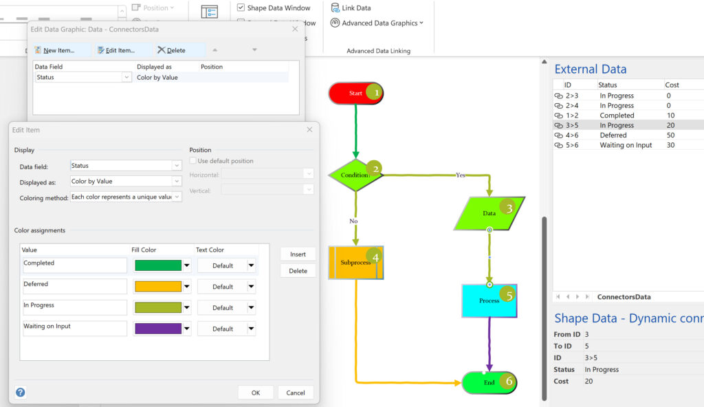
Data Graphics in Visio Plan 2 and Visio Professional is great, but it only enables us to use them with 2D shapes in Visio, i.e. not on connectors. So, what if you want to change the line colour of the connectors between the 2D shapes because of the data flowing between them? Well, it is possible … with a little preparation!
