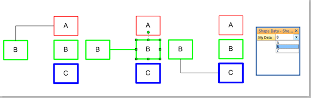
A reader recently asked if I could explain how to programmatically get the shapes connected to a shape in Visio. So, I thought I would have a go, because there are alternatives, depending upon which functions are used, and what parameters are passed to them. The following animated gif is rotating around the different types of selections that can be made from the lower Decision shape. Normally, two 2D shapes are connected together using a 1D shape. The 1D shape has a direction because it starts from “BeginX” and finishes at “EndX”. This is irrespective of an arrowheads that the user may have chosen to adorn the 1D connector with at either end.
Connectors
Getting the Name of Glued Connection Points
A Visio developer asked me if it is possible to get the name of connection points that a connector is glued to in Visio. Well, it is not possible directly from the ShapeSheet, but is easy if you use a little code.
First of all, I created a simple Block shape with 3 named connection points on either side of it. I added a little text to the block to display the shape name, and to remind me where the named connection points are.
[Read more…] about Getting the Name of Glued Connection Points
Adding More Smartness to Visio Connectors
Whenever I have been asked why I like Visio so much, I have usually cited its ability to connect shapes together; its ability to link to data; and its programmability. Visio 2010 formally added a structured diagram concept and API, and the premium edition introduced diagram validation. So many different types of Visio diagrams require elements to be connected together correctly, and I often have to add a little extra into the connectors to make them smarter.
What is a connector?
A connector is a Visio shape that has 1-D behavior. The most used example is the Dynamic connector shape, which not only connects elements together, but can also re-route itself according to the layout and routing options selected for a page.
[Read more…] about Adding More Smartness to Visio ConnectorsWriting rules to validate diagrams in Visio 2010 – A worked example
Microsoft Visio 2010 Premium Edition introduced an extension to the Visio Type Library called the Validation API. This provides the capability to validate a Visio diagram to ensure that its construction complies with industry-standard or company –wide rules.
Organizations are able to use this new feature to encapsulate business logic as validation rules, grouped within rule sets.
Microsoft Visio 2010 Premium edition contains rule sets for use with Basic and Cross-Functional Flowcharts, BPMN Diagrams and SharePoint Workflow Designer diagrams.
This article describes how you can create your own rule sets and rules.
Listing Connections in Visio 2010
One of the best bits of Visio is the connections between shapes, but it has always been difficult to understand these connections in code. There are connections to and from shapes, which require you to understand where you are and which way to look … at the beginning or the end of a 1D connector. Visio 2010 has added some useful extra methods to the shape object which makes understanding connections much easier. This post will show you how you can use the new GluedShapes() and ConnectedShapes() methods.
Take, for example, a network diagram where there are connections between servers and routers:
You may wish to list the connections at the start and end of each cable. Previously, this would have meant inspecting the connected cell to see if was at the beginning or end of the line, but now you can use the GluedShapes() method of a shape to retrieve an array of the 2D shapes connected at one end or another with the relevant arguments, visGluedShapesIncoming2D or visGluedShapesOutgoing2D. The ListGluedConnections macro below displays the following in the immediate window:
Connector Dynamic connector
> Router.45 router-02
< Server server-01 Connector Dynamic connector.107 > Router.45 router-02
< Server.30 server-02 Connector Dynamic connector.108 > Router router-01
< Server.75 server-03 Connector Dynamic connector.109 > Router.91 router-03
< Server.30 server-02 Connector Dynamic connector.110 > Router.91 router-03
< Server server-01
Public Sub ListGluedConnections()
Dim shp As Visio.Shape
Dim connectorShape As Visio.Shape
Dim sourceShape As Visio.Shape
Dim targetShape As Visio.Shape
Dim aryTargetIDs() As Long
Dim arySourceIDs() As Long
Dim targetID As Long
Dim sourceID As Long
Dim i As Integer
For Each shp In Visio.ActivePage.Shapes
If shp.OneD Then
Debug.Print "Connector", shp.Name
arySourceIDs = shp.GluedShapes(visGluedShapesIncoming2D, "")
For i = 0 To UBound(arySourceIDs)
Set sourceShape = Visio.ActivePage.Shapes.ItemFromID(arySourceIDs(i))
If sourceShape.CellExists("Prop.NetworkName", Visio.visExistsAnywhere) Then
Debug.Print , ">", sourceShape.Name, sourceShape.Cells("Prop.NetworkName").ResultStr("")
End If
Next
aryTargetIDs = shp.GluedShapes(visGluedShapesOutgoing2D, "")
For i = 0 To UBound(aryTargetIDs)
Set targetShape = Visio.ActivePage.Shapes.ItemFromID(aryTargetIDs(i))
If targetShape.CellExists("Prop.NetworkName", Visio.visExistsAnywhere) Then
Debug.Print , "<", targetShape.Name, targetShape.Cells("Prop.NetworkName").ResultStr("")
End If
Next
End If
Next
End SubSimilarly, you may want to simply list the next connected 2D shape, effectively ignoring the cable. In this case, you can use the new ConnectedShapes() method, with the relevant arguments visGluedShapesIncoming2D or visGluedShapesOutgoing2D, to produce an output like the following ( using the ListNextConnections macro below):
Shape Server server-01
> Router.45 router-02
> Router.91 router-03
Shape Router router-01
< Server.75 server-03 Shape Server.30 server-02 > Router.45 router-02
> Router.91 router-03
Shape Router.45 router-02
< Server server-01
< Server.30 server-02 Shape Server.75 server-03 > Router router-01
Shape Router.91 router-03
< Server server-01
< Server.30 server-02
Public Sub ListNextConnections()
Dim shp As Visio.Shape
Dim connectorShape As Visio.Shape
Dim sourceShape As Visio.Shape
Dim targetShape As Visio.Shape
Dim aryTargetIDs() As Long
Dim arySourceIDs() As Long
Dim targetID As Long
Dim sourceID As Long
Dim i As Integer
For Each shp In Visio.ActivePage.Shapes
If Not shp.OneD Then
If shp.CellExists("Prop.NetworkName", Visio.visExistsAnywhere) Then
Debug.Print "Shape", shp.Name, shp.Cells("Prop.NetworkName").ResultStr("")
arySourceIDs = shp.ConnectedShapes(visConnectedShapesOutgoingNodes, "")
For i = 0 To UBound(arySourceIDs)
Set sourceShape = Visio.ActivePage.Shapes.ItemFromID(arySourceIDs(i))
If sourceShape.CellExists("Prop.NetworkName", Visio.visExistsAnywhere) Then
Debug.Print , "<", sourceShape.Name, sourceShape.Cells("Prop.NetworkName").ResultStr("") End If Next aryTargetIDs = shp.ConnectedShapes(visConnectedShapesIncomingNodes, "") For i = 0 To UBound(aryTargetIDs) Set targetShape = Visio.ActivePage.Shapes.ItemFromID(aryTargetIDs(i)) If targetShape.CellExists("Prop.NetworkName", Visio.visExistsAnywhere) Then Debug.Print , ">", targetShape.Name, targetShape.Cells("Prop.NetworkName").ResultStr("")
End If
Next
End If
End If
Next
End SubI think this makes interrogation of connected diagrams, of all flavours, much simpler, though I would love to have similar ShapeSheet functions too!
Setting Visio Shape Cell Values By Connections
A recent newsgroup poster asked me to explain how to set the line color and weight of a connector according to the shapes it is connected to. So, in this article, I have tried to explain one method of achieving this with minimal external coding.
In this example, I have created a rectangle shape that has a single Shape Data row, MyData, which has a fixed list of values, A;B;C.
The connector shape has been modified to trigger an event whenever a connection is made or unmade. If the user successfully connects two rectangles with the same MyData value, then the line (weight and color) of the connector shape is amended to match the rectangle shapes.

[Read more…] about Setting Visio Shape Cell Values By Connections
