I have previously tackled the subject of snapping to grids in Visio desktop (see https://bvisual.net/2018/06/19/really-snapping-to-grids-in-visio/ ) but a recent project required me to improve the example because it did not respond to all cursor arrow keys. The problem was that the previous solution could not understand which arrow key had been clicked, therefore it did not know if to reposition to the previous or next grid. The new ShapeSheet code solution can now respond to the correct arrow key … and all without any add-in. In addition, I also show how a Control point can be made to snap to a grid spacing, and how AutoConnect can be set to add the next shape at the right offset in both the horizontal and vertical directions.
Lastly, Microsoft released the web edition of Visio since the last article, and I demonstrate the difference behaviour of grid snapping between that and the desktop edition.
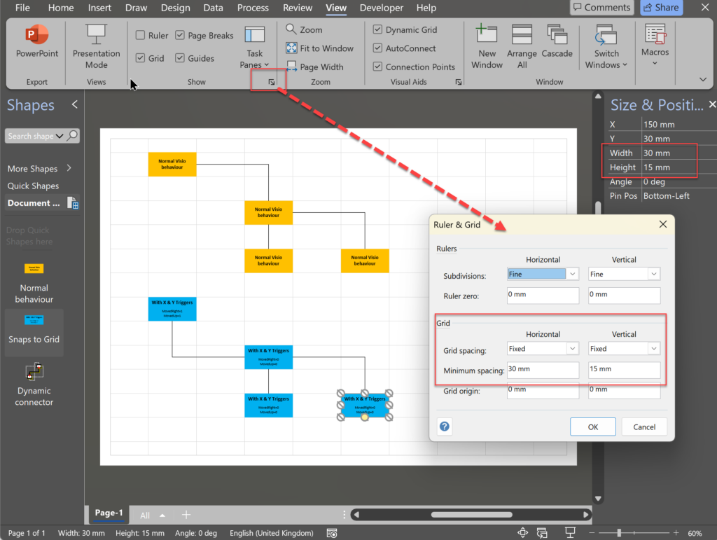
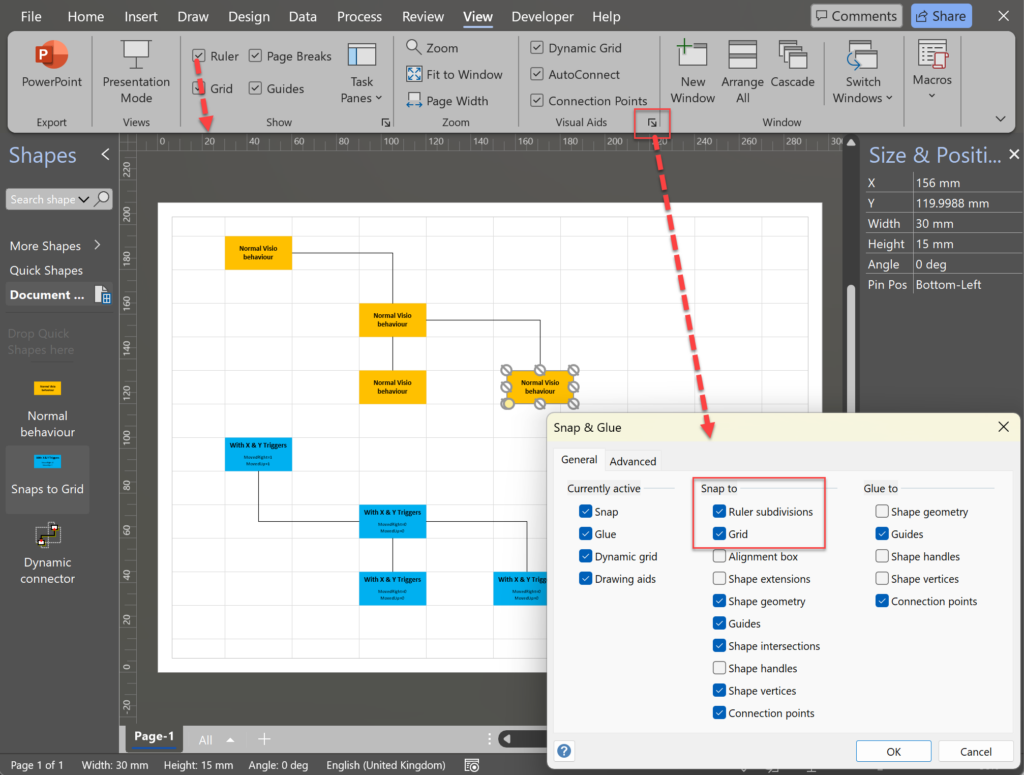
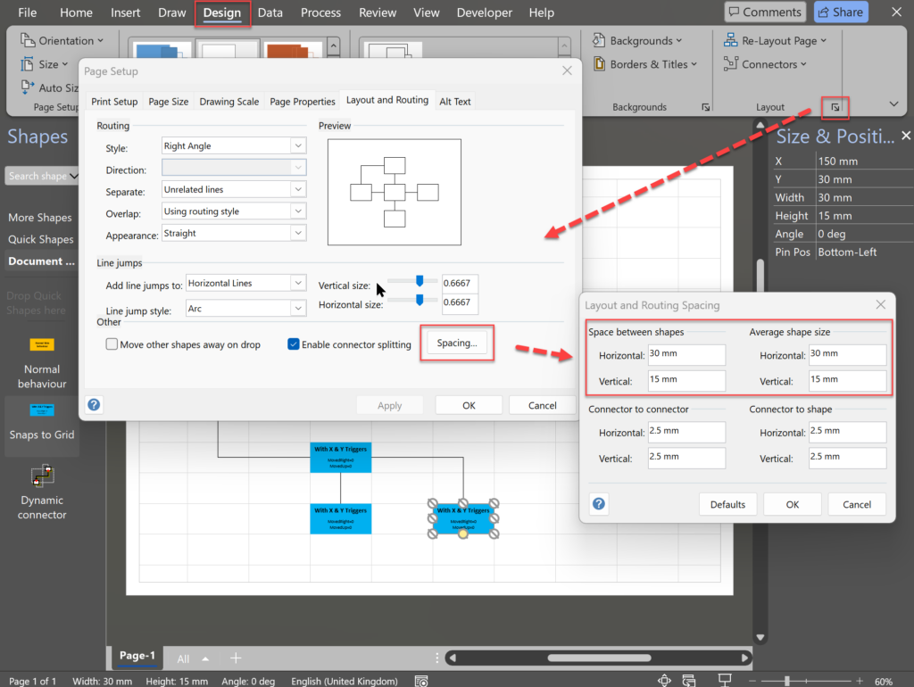
The following video shows how the Visio page and settings can be edited to provide snapping to grids in Visio desktop. In this example, the average shape size is 30 mm wide and 15 mm high, and the grid is fixed to 30 mm horizontal spacing and 15 mm vertical spacing. The Rulers Subdivisions are irrelevant because ruler snapping needs to be turned off for the grid snapping to work effectively.
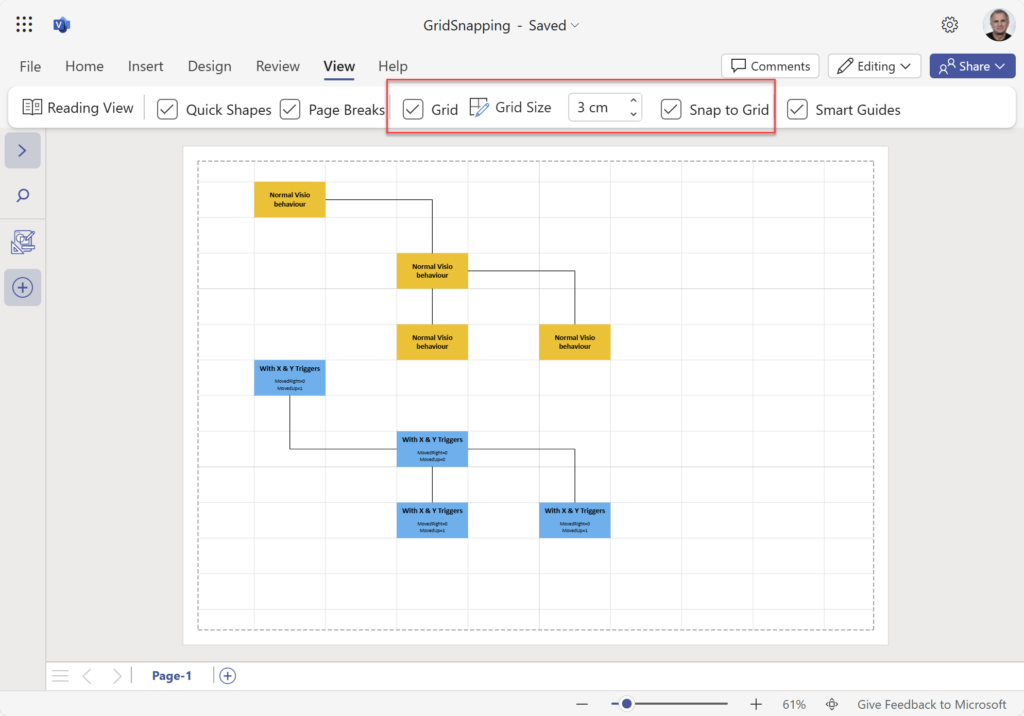
The behavour of grid snapping in Visio for the Web is a little different, and better by default, but there is something lacking …. Visio for the Web only has one value to to change for both the X and Y grid spacing.
The online bevahiour is slightly different,as can be seen in the video below. There is no ruler view and therefore no ruler snapping.
Preparing the Page
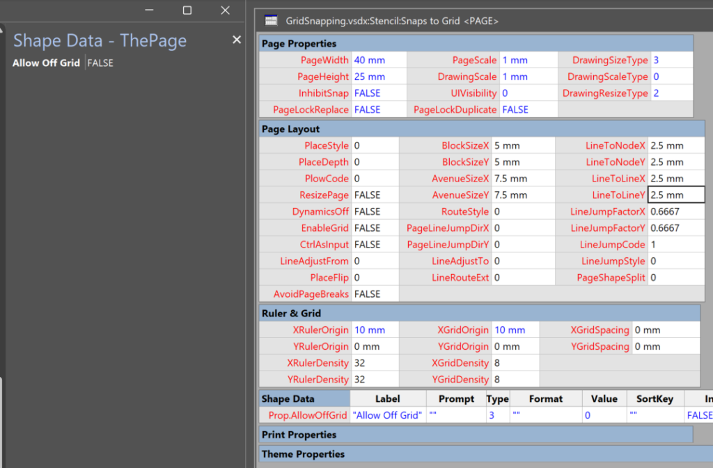
I decided that I should provide the ability to switch off the forced grid snapping of the shape by providing a TRUE/FALSE Shape Data row in the page. I called this AllowOffGrid, and when this is TRUE, then the shape should not be forced to the fixed grid, but simply respect the normal Visio behaviour.
Preparing the master shape
This grid snapping does require some preparation of the master shape with some ShapeSheet formulas. The main difference with this revised code is the ability to recognise the direction that a keyboard arrow press has dictated. However, the shape may also be dragged and dropped into a location using the mouse, so the formulas need to respond to either scenario. A third scenario is that a shape is positioned via automation, and this might be accidently off-grid, so the shape needs to re-position itself automatically.
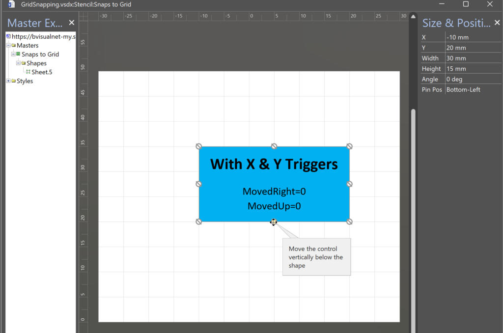
In this example, I have prepared the Master page (right mouse selection from the Snaps to Grid element in the Master Explorer window) with a Fixed grid spacing of 5 mm. It does not need to be the same spacing as the page that it will be dropped on to. Also, I have set the Pin Pos of the shape to the Bottom Left (LocPinX = 0 and LocPinY = 0), although this is not essential, but rememember that the snapping is based on the this point within the shape.
Note that I have split the cell formulas over several lines in the code panels below, but these can be copied and pasted into the Edit Formula multi-line dialog avaiable in each cell.

EventXFMod
This was the main missing element from my previous solution, as it provides the ability to capture the previous position, using GETVAL(…), just before the movement happens. Every Visio shape has this cell, and it will get evaluated each time the shape is moved. It is used here to use the previous PinX and PinY values just before the User.MovedUpTrigger and User.MovedRightTrigger cells evaluate. The formula will set the User.MovedRight cell value to 1, using SETF(…) and GETREF(…), if the shape is moved to the right, or 0 if the shape is moved to the left. Similarly, it will set the User.MovedUp cell value to 1 if the shape is moved upwards, or 0 if moved downwards.
=SETF(GetRef(User.MovedRight),User.LastPinX<PinX)
+SETF(GetRef(User.LastPinX),"=GETVAL(PinX)")
+SETF(GetRef(User.MovedUp),User.LastPinY<PinY)
+SETF(GetRef(User.LastPinY),"=GETVAL(PinY)")
User.Offset
I introduced this as a User-defined Cell because it provides the ability to test different values for effectiveness. It needs to be a number beyween 0 and 1, and it is the offset factor to create a zone from the top, bottom, left or right, within which the User.YGridTrigger or User.XGridTrigger will evaluate.
User.MovedRight
Compares the previous value of PinX with the new value, and puts the result in User.LastPinX, resulting in 1 if the shape moved right, or 0 if it moved left.
User.LastPinX
Holds the result of the User.MovedRight action
User.MovedUp
Compares the previous value of PinY with the new value, and puts the result in User.LastPinY, resulting in 1 if the shape moved up, or 0 if it moved down.
User.LastPinY
Holds the result of the User.MovedUp action
User.MovedUpTrigger
This will update the PinY cell value to so that is it is on a grid, if it is found to be within the middle part of a vertical grid.
=IF(
 OR(
  ThePage!Prop.AllowOffGrid,
  MODULUS(ThePage!YGridOrigin-PinY,ThePage!YGridSpacing)=0,
  User.LastPinY<>PinY
 ),
 0,
 IF(
  AND(
   MODULUS(ThePage!YGridOrigin-PinY,ThePage!YGridSpacing)<=(1-User.Offset)*ThePage!YGridSpacing,
   MODULUS(ThePage!YGridOrigin-PinY,ThePage!YGridSpacing)>=User.Offset*ThePage!YGridSpacing
  ),
  IF(
   NOT(User.MovedUp),
   SETF(GetRef(PinY),
    ThePage!YGridOrigin-FLOOR((ThePage!YGridOrigin-PinY)/ThePage!YGridSpacing)*ThePage!YGridSpacing
   ),
   SETF(GetRef(PinY),
    ThePage!YGridOrigin-CEILING((ThePage!YGridOrigin-PinY)/ThePage!YGridSpacing)*ThePage!YGridSpacing
   )
  ),
  0
 )
)
User.MovedDownTrigger
This will update the PinX cell value to so that is it is on a grid, if it is found to be within the center part of a horizontal grid.
=IF(
 OR(
  ThePage!Prop.AllowOffGrid,
  MODULUS(ThePage!XGridOrigin-PinX,ThePage!XGridSpacing)=0,
  User.LastPinX<>PinX
 ),
 0,
 IF(
  AND(
   MODULUS(ThePage!XGridOrigin-PinX,ThePage!XGridSpacing)<=(1-User.Offset)*ThePage!XGridSpacing,
   MODULUS(ThePage!XGridOrigin-PinX,ThePage!XGridSpacing)>=User.Offset*ThePage!XGridSpacing
  ),
  IF(
   NOT(User.MovedRight),
   SETF(GetRef(PinX),
    ThePage!XGridOrigin-FLOOR((ThePage!XGridOrigin-PinX)/ThePage!XGridSpacing)*ThePage!XGridSpacing
   ),
   SETF(GetRef(PinX),
    ThePage!XGridOrigin-CEILING((ThePage!XGridOrigin-PinX)/ThePage!XGridSpacing)*ThePage!XGridSpacing
   )
  ),
 0)
)
User.YGridTrigger
This will update the PinY cell value to so that is it is on a grid, if it is found to be within the top or bottom part of a vertical grid.
=IF(
 OR(
  ThePage!Prop.AllowOffGrid,
  MODULUS(ThePage!YGridOrigin-PinY,
  ThePage!YGridSpacing)=0
 ),
 0,
 IF(
  MODULUS(ThePage!YGridOrigin-PinY,ThePage!YGridSpacing)>(1-User.Offset)*ThePage!YGridSpacing,
  SETF(GetRef(PinY),
   ThePage!YGridOrigin-FLOOR((ThePage!YGridOrigin-PinY)/ThePage!YGridSpacing)*ThePage!YGridSpacing
  ),
  IF(
   MODULUS(ThePage!YGridOrigin-PinY,ThePage!YGridSpacing)<User.Offset*ThePage!YGridSpacing,
   SETF(GetRef(PinY),
    ThePage!YGridOrigin-CEILING((ThePage!YGridOrigin-PinY)/ThePage!YGridSpacing)*ThePage!YGridSpacing
   ),
  0
  )
 )
)
User.XGridTrigger
This will update the PinX cell value to so that is it is on a grid, if it is found to be within the left or right part of a horizontal grid.
=IF(
 OR(
  ThePage!Prop.AllowOffGrid,
  MODULUS(ThePage!XGridOrigin-PinX,ThePage!XGridSpacing)=0
  ),
  0,
  IF(
   MODULUS(ThePage!XGridOrigin-PinX,ThePage!XGridSpacing)>(1-User.Offset)*ThePage!XGridSpacing,
   SETF(GetRef(PinX),
    ThePage!XGridOrigin-FLOOR((ThePage!XGridOrigin-PinX)/ThePage!XGridSpacing)*ThePage!XGridSpacing),
   IF(
   MODULUS(ThePage!XGridOrigin-PinX,ThePage!XGridSpacing)<User.Offset*ThePage!XGridSpacing,
   SETF(GetRef(PinX),
    ThePage!XGridOrigin-CEILING((ThePage!XGridOrigin-PinX)/ThePage!XGridSpacing)*ThePage!XGridSpacing
   ),
   0
  )
 )
)
Controls.Row_1.Y
I set the X position of the control to be at the bottom center of the shappe initially, and prevented any horizontal movement by setting the X Behavior value to 1. The Y Behavior is left at 0 to allow manual positioning, but the BOUND(..) function that i have added to the Y value restricts it’s movement to specific positions.
This formula is to force the control point to snap to one of four positions at a multiple of the YGridSpacing at or below the bottom edge of the shape. This formula can be extended to provide snapping to many more grid spacing positions.
=BOUND(
 Height*0,
 0,
 FALSE,
 Height*0,
 Height*0,
 FALSE,
 Height*0-1*ThePage!YGridSpacing,
 Height*0-1*ThePage!YGridSpacing,
 FALSE,
 Height*0-2*ThePage!YGridSpacing,
 Height*0-2*ThePage!YGridSpacing,
 FALSE,
 Height*0-3*ThePage!YGridSpacing,
 Height*0-3*ThePage!YGridSpacing
)
Conclusion
These formulas will force the shape to snap to the grid when the page Allow Off Grid is FALSE, regardless of whether or not the grid lines are displayed, but does require Visio grid snapping on.
However, the page Allow Off Grid should be set to TRUE if the shape needs to behave just like anyother shape with respect to normal Visio document grid snapping. In my actual project I ensure that grid snapping is enabled ( see https://learn.microsoft.com/office/vba/api/visio.document.snapenabled ), and grid snap is on but ruler snapping is off ( see https://learn.microsoft.com/office/vba/api/visio.document.snapsettings). This has to be done with automation since these settings are not available in ShapeSheet formula.
The example document can be downloaded from https://bvisualnet-my.sharepoint.com/:u:/g/personal/davidp_bvisual_net/EbSRuFA3LX1FsfR2p-Ros9sBsMS4av4uPoow4gQGb7q42Q?e=RIqXXF
See eVSM to learn more about the project I am working on.
Related Articles
Jumping between Shapes in Visio
Many Visio diagrams get quite large, and sometimes it is useful to provide the ability to jump to another shape quickly in the same document, either on a different page or on the same one. Although there is an add-on provided in desktop Visio that is used by the Off-Page Reference shape provided in the…
Fixing dimensions of 2D shapes
I am often asked what makes Visio unique and makes it stand out from the crowd, especially in today’s online world. Well, I think there are many reasons, but one of them is the ability to create scaled drawings with parametric components of specific dimensions. This was crucial for my adoption of Visio back in…
Smart Radio Buttons and Check Boxes in Visio
A recent project requires an interactive tutorial within Microsoft Visio desktop where a lot of the questions need a single answer using radio buttons, or multiple-choice answers using check boxes. I thought that this would be a great use of the list containers capability because the questions and answers could be part of the container…
Using Button Face Ids in Visio
Microsoft Visio desktop has the ability to display icons from a built-in list of Office icons on Actions and Action Tags (nee Smart Tags). These can be set in the ShapeSheet by using the desired number from several thousand in the ButtonFace cell. Although there is the ability to add better icons using code, the…
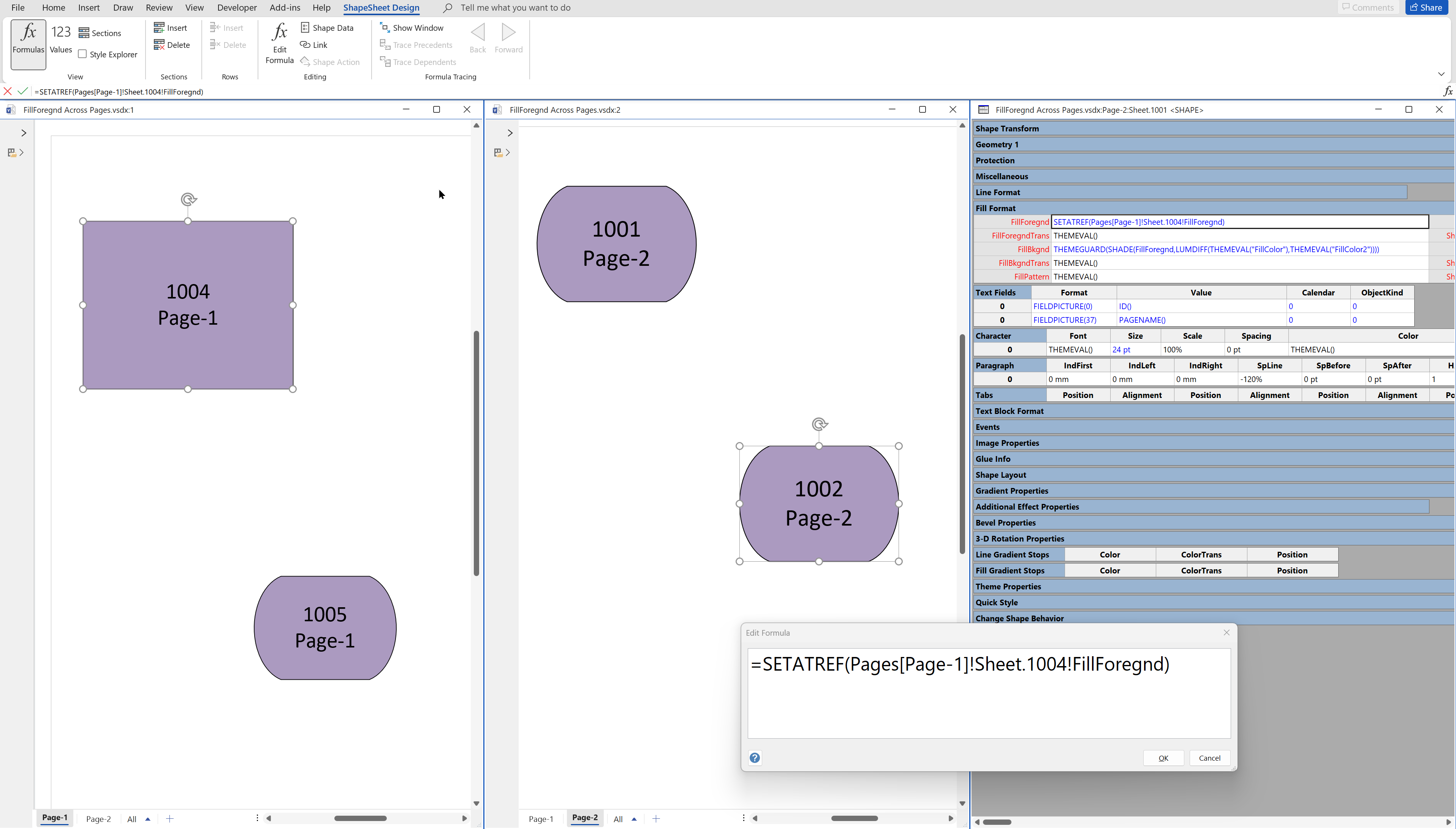
Synchronizing Visio Shape Fill Color (or almost any cell) across pages
I was recently asked how the color of one shape can be changed and for other shapes to be automatically updated to the same color … even if they are on different pages! Well, it is possible with Microsoft Visio’s awesome ShapeSheet formulas. In fact, this capability is not limited to the FillForegnd cell ……
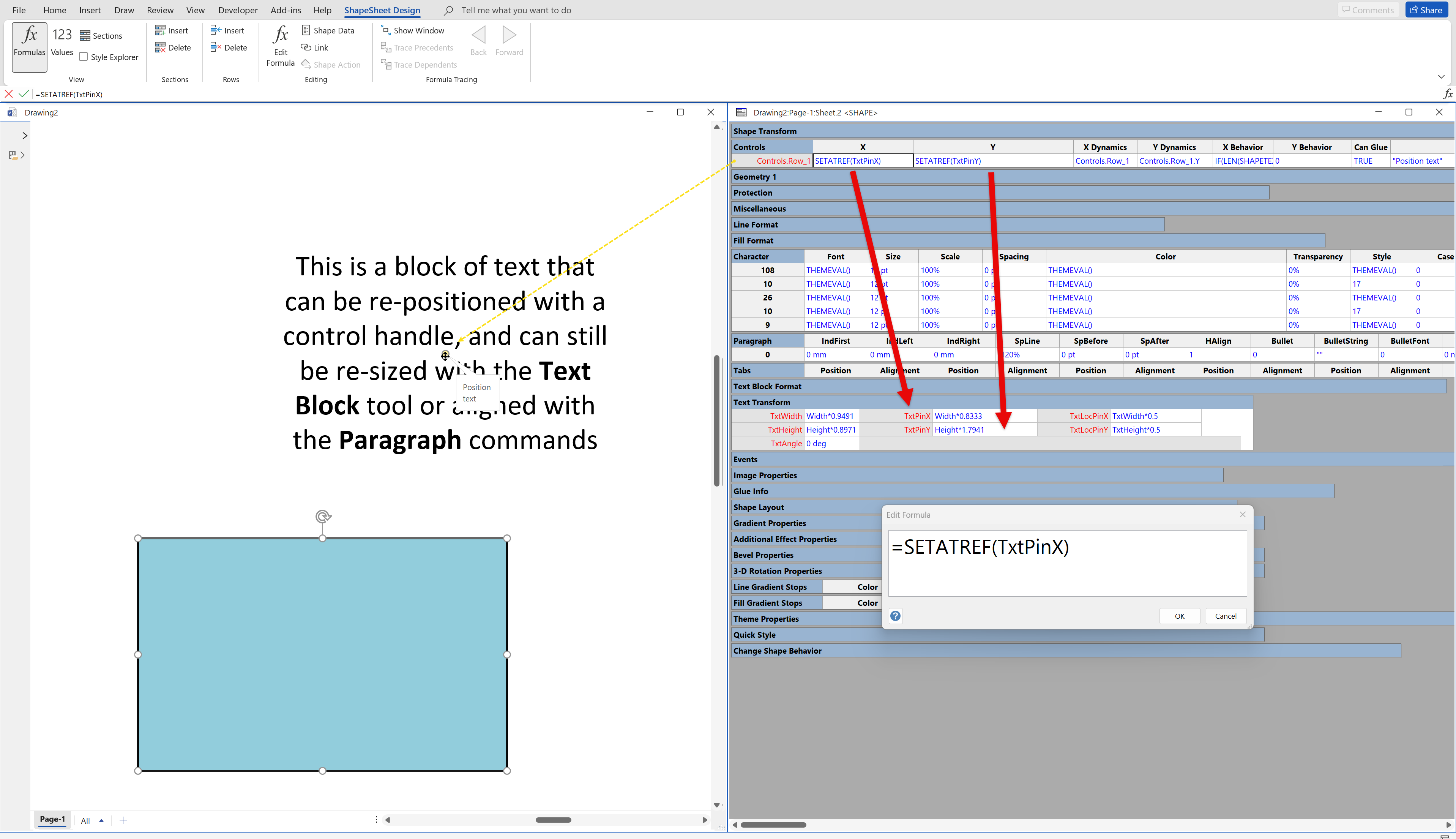
Positioning Visio Shape Text Block with a Control Handle
I was recently asked how a control handle can be added to a Visio shape so that it can be used to re-position the text block. Fortunately, it is extremely easy to setup, and requires just two formulas to be updated in the ShapeSheet. This is a great use of the SETATREF(…) function. (more…)

Leave a Reply
You must be logged in to post a comment.