Whenever I have been asked why I like Visio so much, I have usually cited its ability to connect shapes together; its ability to link to data; and its programmability. Visio 2010 formally added a structured diagram concept and API, and the premium edition introduced diagram validation. So many different types of Visio diagrams require elements to be connected together correctly, and I often have to add a little extra into the connectors to make them smarter.
What is a connector?
A connector is a Visio shape that has 1-D behavior. The most used example is the Dynamic connector shape, which not only connects elements together, but can also re-route itself according to the layout and routing options selected for a page.
Verifying that a connector is actually connected
If you look at the ShapeSheet of a connector, you will see that the 1-D Endpoints section has formulas for the Begin and End X/Y co-ordinates. Additionally, there are special trigger formulas in the Glue Info section.

Note that the screenshots in this blog are from Visio 2010, where red is used to indicate a connection; however, Visio 2013 has changed this to a green display because too many people associate red with some sort of error.
If one end of a connector is disconnected, then you can see that the formulas in the 1-D Endpoints and Glue Info sections change:

However, if you look at the values of the Glue Info cells, you can see that a connected end has a value of 2, but a disconnected end has a value of 1 (or possibly 0 if it has never been connected).

Thus, you could use the values in the BegTrigger and EndTrigger cells to check if a connector is actually connected at either or both ends. The next decision is how you intend to visualise the result with just ShapeSheet formulas – line pattern, line arrow, line color, text or something else? If you allow users to vary the line format, then perhaps pattern, arrow and color should not be set with ShapeSheet formulas. Text on connectors could be used for some other purpose, so what’s left?
Well, I would suggest this could be a good use of Action Tags because they are only visible in Visio.
So, I made some amendments to the Dynamic connector master in my document:
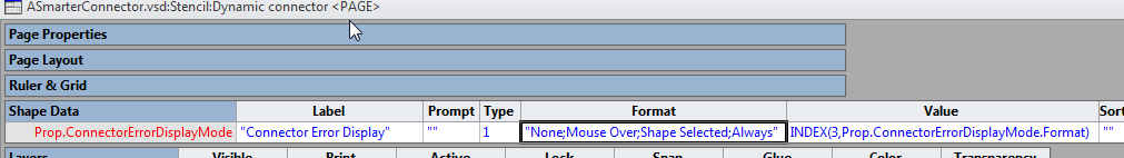
First, I added a Fixed List (1) Type Shape Data row, Prop.ConnectorErrorDisplayMode, to its page with the Format =”None;Mouse Over;Shape Selected;Always”
I then added two Action Tags rows to the shape, one for the possible misconnection at the start of the line, and one for the end:

I set the DisplayMode formula to lookup its value from the Shape Data row that I created in the page of the master:
=LOOKUP(ThePage!Prop.ConnectorErrorDisplayMode,ThePage!Prop.ConnectorErrorDisplayMode.Format)-1
This formula will actually return the values 255,0,1 or 2, and I happily discovered that any value except 0,1 or 2 will render the action tag row invisible.
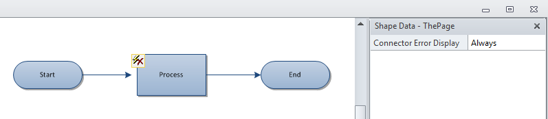
When the Dynamic connector is used in the diagram, then you can get a more visible display of any error connection errors:
I also included a formula in the Description cell of each Action Tags row so that it would appear as a screen tip in Visio:
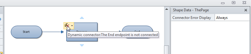
By the way, Action Tags are always the same size, regardless of your zoom level so you can spot connection errors even when zoomed right out.
What is the flow direction?
In some types of diagram, it is important to get the flow direction correct, especially if Visio is to be used as the source of a data export to some other application.
The above screenshots were taken whilst a theme was applied, which provided the arrow at the end of each connector, however, if the user chooses to have no theme, then it is impossible to tell which way the connector is flowing:

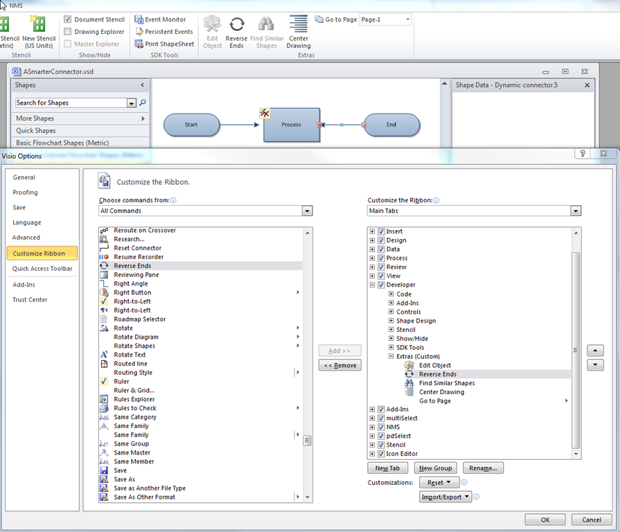
So, I think it is useful to either preset the end arrow of your connector, or to use a theme which displays the flow direction. In any case, there is a Visio command, Reverse Ends, that can be added to your ribbon in order to provide the ability to easily switch a line flow direction.
Those of you who have been following my blog may have already worked out where I am going with this ….
Great !
Where could I download this connector shape ?
Got it to work. Thanks. But there is a problem..
When i delete a shape with connectors on it the connectors Begin and End triggers in the shapesheet still show the same value, and therfore the “not connected” icons don’t show.
Is it possible to run som code when a shape is deleted and trig something that makes this work again ?
If you delete a 2D shape, then Visio can automatically delete any connectors that are connected to it, if you have File \ Options \ Advanced \ Delete connectors when deleting shapes is ticked.
If you don’t have this ticked, then I cannot think of a way to detect if the connector has lost its connected shape, because Visio automatically replaces the BegTrigger or EndTrigger cell formula with 2, which is the same value if it is connected, until the connector end is actually moved. It then changes to 1, which is correct for unconnected.
Hi,
Is there any way that I can set a connector to not delete when the connected shape is deleted? The setting in Visio for DeleteConnectorsEnabled is enabled.
Thanks,
Naresh
Surely you just untick that option in File / Options / Advanced ?
Works for me.
Hi,
I’ve never really liked that shapes have so few connecting points. Knowing that my project was going to have several connectors going back a fore among shapes, I went ahead and added multiple connection points, planning that the connectors would have a multitude of connecting points to choose from (dragging the connectors’ heads deep inside the shape and the whole shape gets a surrounding red line) and not have all connectors go in and out from the 4 basic connecting points of the shape.
Well, it doesn’t really work, and I cannot understand why. The connectors keep going in and out of the 4 basic connecting points of the shape, they ignore the added connecting points I added.
Any ideas?
Thanks,
Ismael.
What version of Visio are you using? The affirmation of a valid connection changed from red to green a couple of versions ago.
Also, a few years ago I had a client who had a similar complaint … he wanted to have multiple connectors in order to ensure separation of connector lines … my solution was to remove ALL connection points and edit the settings in Page Setup / Layout & Routing so that no two connector lines were coincident.
I’m using Visio 2010.
I’ve used it some, I understand how to tell the connector is actually glued (red) to a shape or not (blue). Even if the connector is glued to a shape as an “auto-select” connection point (red/white square), or manually glued to a specific point (red square).
I have not tried the solution you describe, but can give it a shot. What did yo change in the Layout & Routing options?
Yes, I do want connectors NOT to coincide, to re-route when I move shapes around to exit through the nearest points on the shapes, but also to route cleanly. For example, if two shapes are located diagonally from each other and two connectors run between them, the connectors likely run one from the top (or bottom – depending on which of the two shapes) and another from one of the sides, but they end up crossing themselves for some reason as they run towards the other shape. I don’t think it is because I’m using curved connectors.
Routing / Separate / All lines
Routing / Overlap / No lines
Routing / Spacing / … play with them!
You can also have apparently invisible shapes that cause the connectors to route around them …
Nop…. The shapes without connection points force the connectors to glue to the shape line. This locks connectors to fix locations, thus does not allow the flexibility of moving shapes around and connectors to choose a more direct path between shapes. Allowing the connectors to “auto-route” in and out of the shape, makes ALL connectors go through the same single point or one of the 4 locations of where the basic connection points typically are, depending on the direction the connector goes.
I made the changes to the Layout and routing for connector to connector portion, but that did not changed a thing.
It is possible to transmit the value from beginX of dynamic connector to Endx. Idea is to have cascading AND gates. Then I change the input of first AND gate and get the output at last AND gate
This is not possible without some code. In other words, there is no ShapeSheet functions available to do this.