Introduction
The Microsoft Power Platform is getting a lot of attention these days, quite rightly, because of it’s ability to provide data storage, entry, process, analysis and prediction.
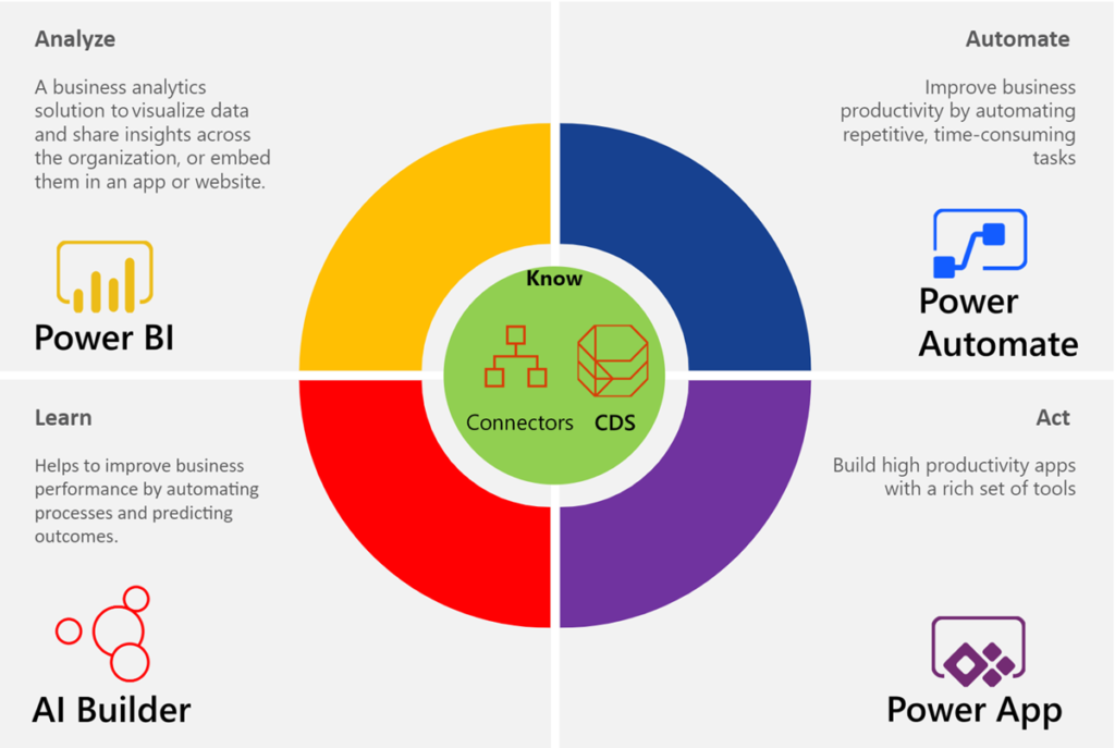
Power Automate, nee Microsoft Flow, is key component of this eco-system, an, although it is growing rapidly to provide the automation of many tasks, it can be difficult to analyse and plan these processes. Indeed, it is unlikely that a business process analyst will have the technical skillset to create and detail complex flows directly within Power Automate.
Microsoft Visio, on the other hand, is a very familiar tool for many business process analysts, and it provides many different types of process flow diagramming templates, and there are hundreds more developed within Visio by third parties. Microsoft Visio Plan 2 now has the ability to create Business Process Management Notation (BPMN) diagrams that can be turned into Power Automate flows automatically. This means that the workflow can be segmented, and can be targeted at the relevant professionals as it passes through the analysis, synthesis and design phases.
Moreover, Visio Data Visualizer feature has the ability to automatically create flow diagrams from an Excel table, either native or via Power Query, and this can be customised to use the BPMN shapes, therefore allowing many types of process lists to be the source of a diagram that can create Power Automate flows automatically. See the demonstration by Scott Helmers in the Microsoft Ignite session from Nov. 2019 at Design and create business workflows automatically using Microsoft Excel, Flow, and Visio and my article Using the Visio Data Visualizer in Excel.
Creating a Visio process diagram for Power Automate
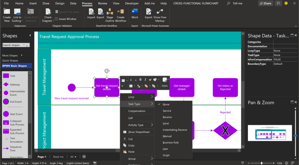
The Microsoft Flow Diagram template in the Flowchart category is the place to start to create a BPMN diagram in Visio Plan 2, that can be exported to Power Automate. It also provides three sample flows, if you need to get familiarised with their structure.
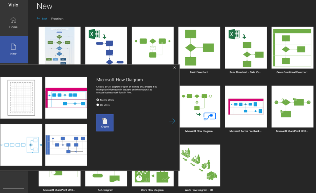
By the time you read this article, Microsoft may have updated the name of template to reflect the recent change of name from Microsoft Flow to Power Automate.
See Design an automated workflow in Visio for more information.
You can also start a Visio BPMN diagram from the Templates section of the Power Automate portal too, and in this case, there are four sample diagrams to review.
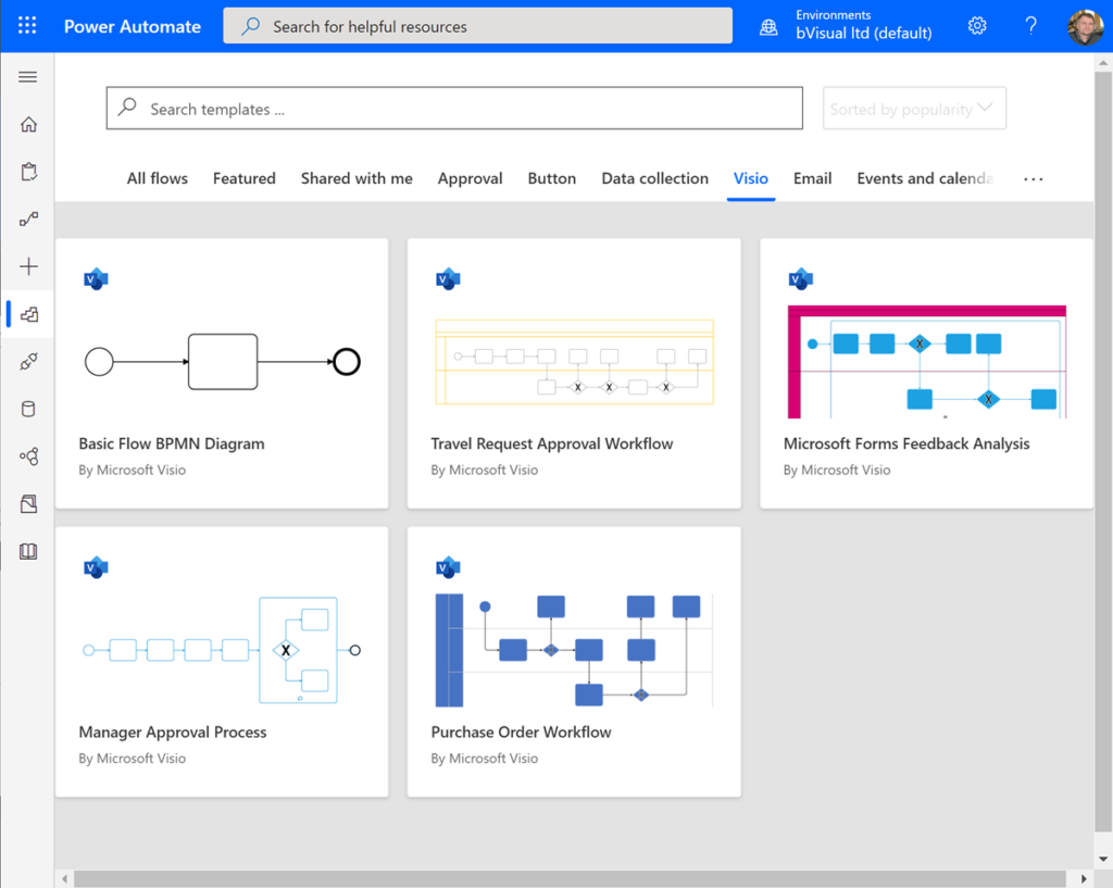
See Design flows in Microsoft Visio for more information about this. In either case, the BPMN Visio diagram can first be created as a normal process flow diagram, and the BPMN shapes laid down, connected, and detailed with the relevant Shape Data values.
Validating the diagram
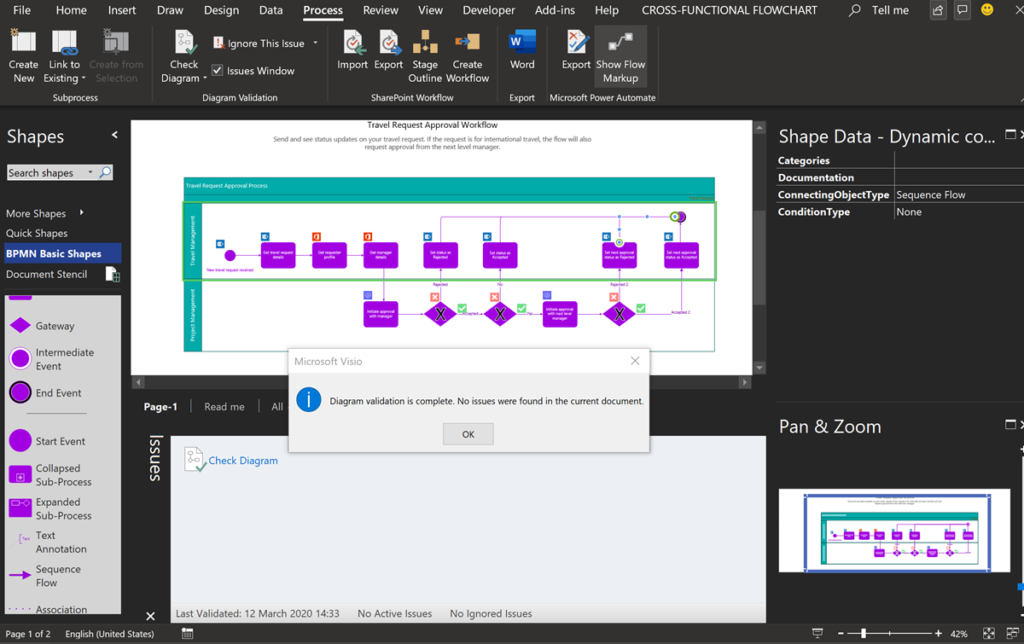
I used the sample Travel Request process for this article and was disappointed to find that the author of the diagram had not checked that it validates according to the BPMN 2.0 rule set, which is available in Visio Plan 2 and Visio Professional.
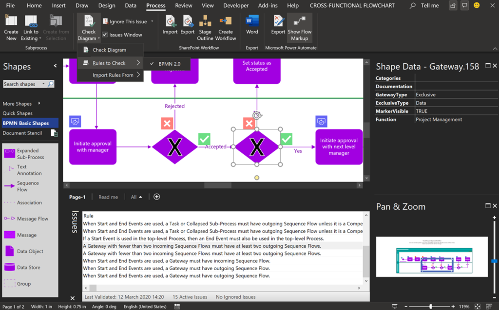
Validation was introduced for the previous Export to SharePointWorkflow feature, but can be applied to many scenarios where a well-constructed diagram is essential. Check out https://bvisual.net/products/rules-tools-for-visio/ for more information.
Export to Word
It is also worth noticing that Visio Plan 2 can export these flow diagrams to Microsoft Word too.
It creates a structured, navigable document with embedded images for each relationship, and tables created from the Shape Data of each shape.
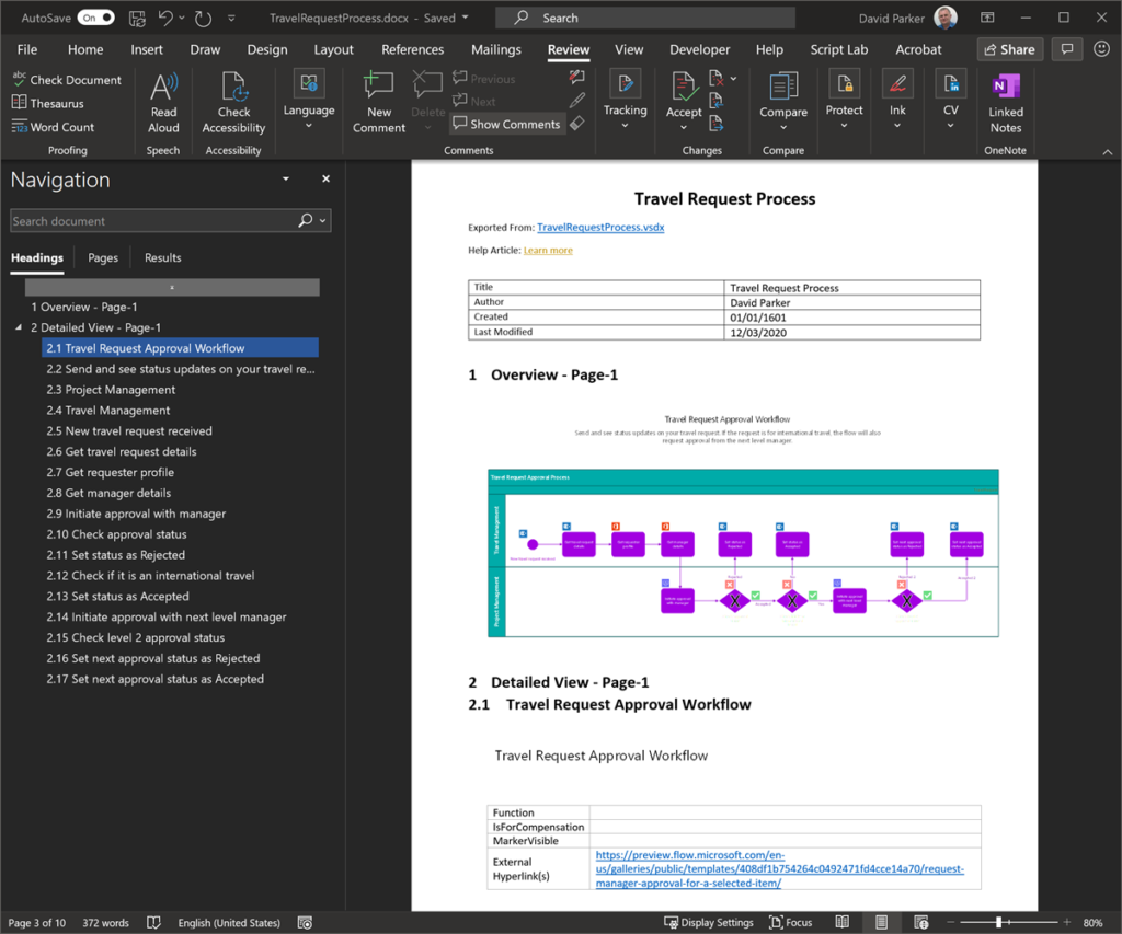
This can be invaluable for documenting and communicating process flows.
Presenting process flows
Visio Plan 2 also can create Slide Snippets that are just rectangular areas, with an optional caption.
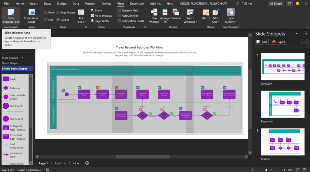
These can be exported to PowerPoint, where it can be enhanced for presentations.
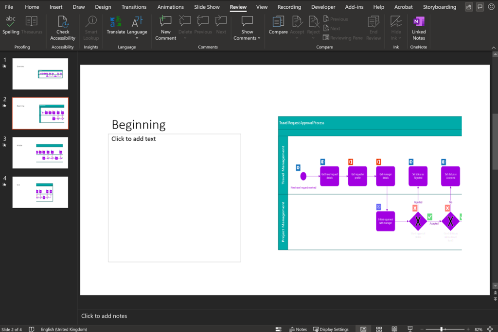
It would be nice if Microsoft enhanced this feature to include a description for each Slide Snippet that can also be exported to PowerPoint, and maintained the aspect ratio of each exported image.
Mapping the Process shapes to Power Automate
Use out-of-the-box Visio shapes to easily capture business processes and input Flow triggers, actions, and connectors. The Microsoft Power Automate / Export button opens the Export panel where the flow triggers and actions can be mapped to each shape.
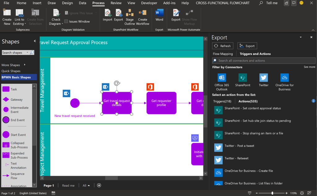
All of the Power Automate Triggers and Actions can be searched to map to each flow shape.
Sequence Flow shapes coming out of Gateway shape should be suitably annotated, and then, the Map Conditions section of the Export panel is used to specify which one is Yes or No.
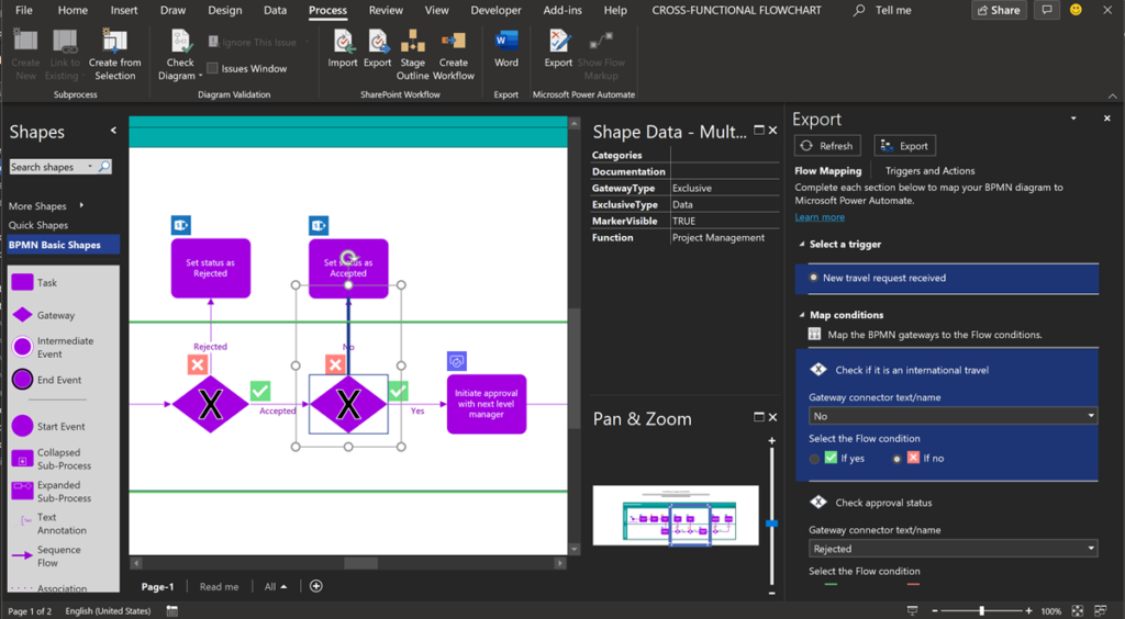
If you map all of the triggers, actions and conditions, then you can press the Export button, where you will be invited to name the flow.
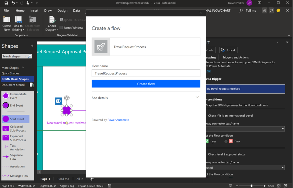
Note that you can re-use the same diagram to create multiple similar flows, but with different details. You can even share a Visio diagram with others, and they can create their own flows, provided they have the right Visio and Power Automate licences.
This will create the flow in MyFlows in your flow.microsoft.com portal.
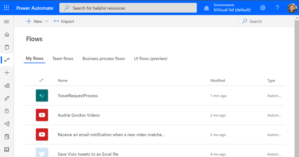
The exported flow can then be edited to add the detail for each step.
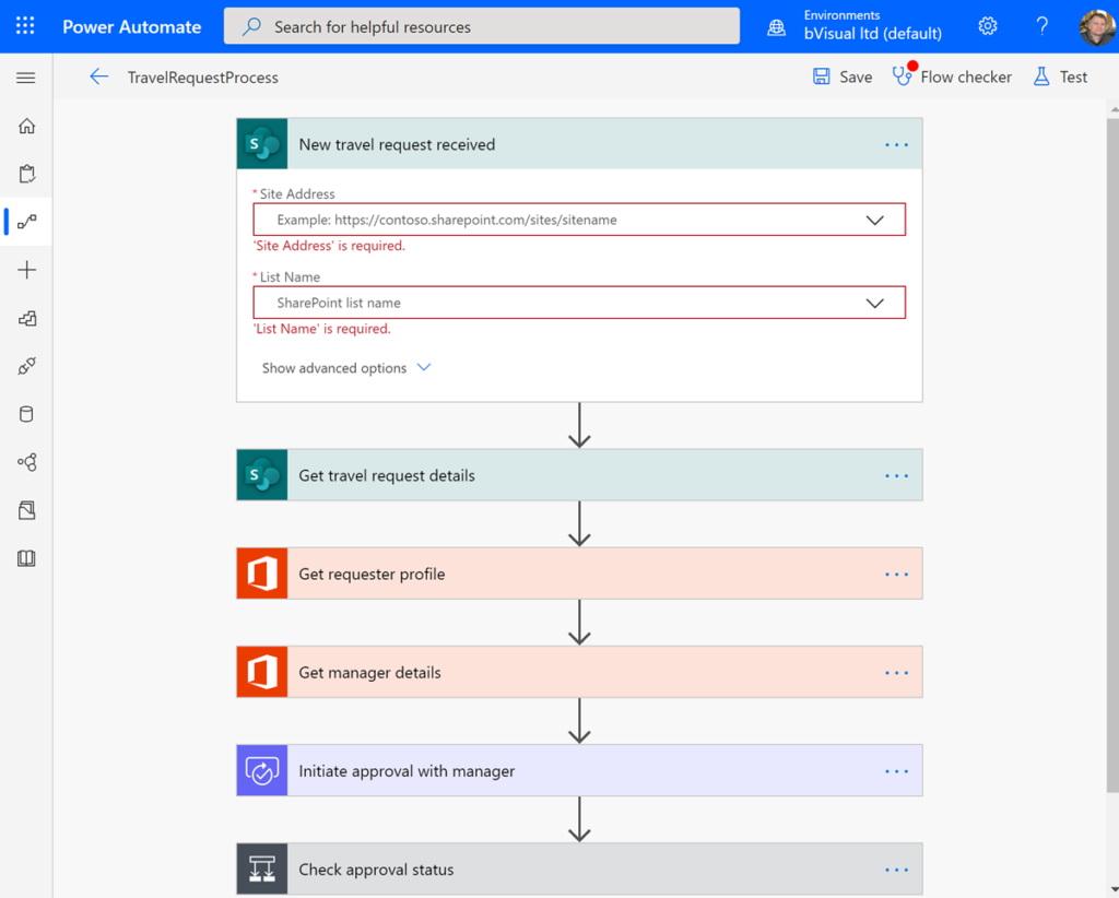
Therefore, Visio can be used to design Power Automate templates that can be detailed for particular tenants and users.
I look forward to the Microsoft Visio team adding the reverse engineering of existing Power Automate flows, since this is a feature I often hear requested…. You can watch more about the future in this other recording from Microsoft Ignite 2019 : Visio roadmap: Now and beyond.
You can read more about more integrations with more of the Power Platform at Visio Visual In Power BI.
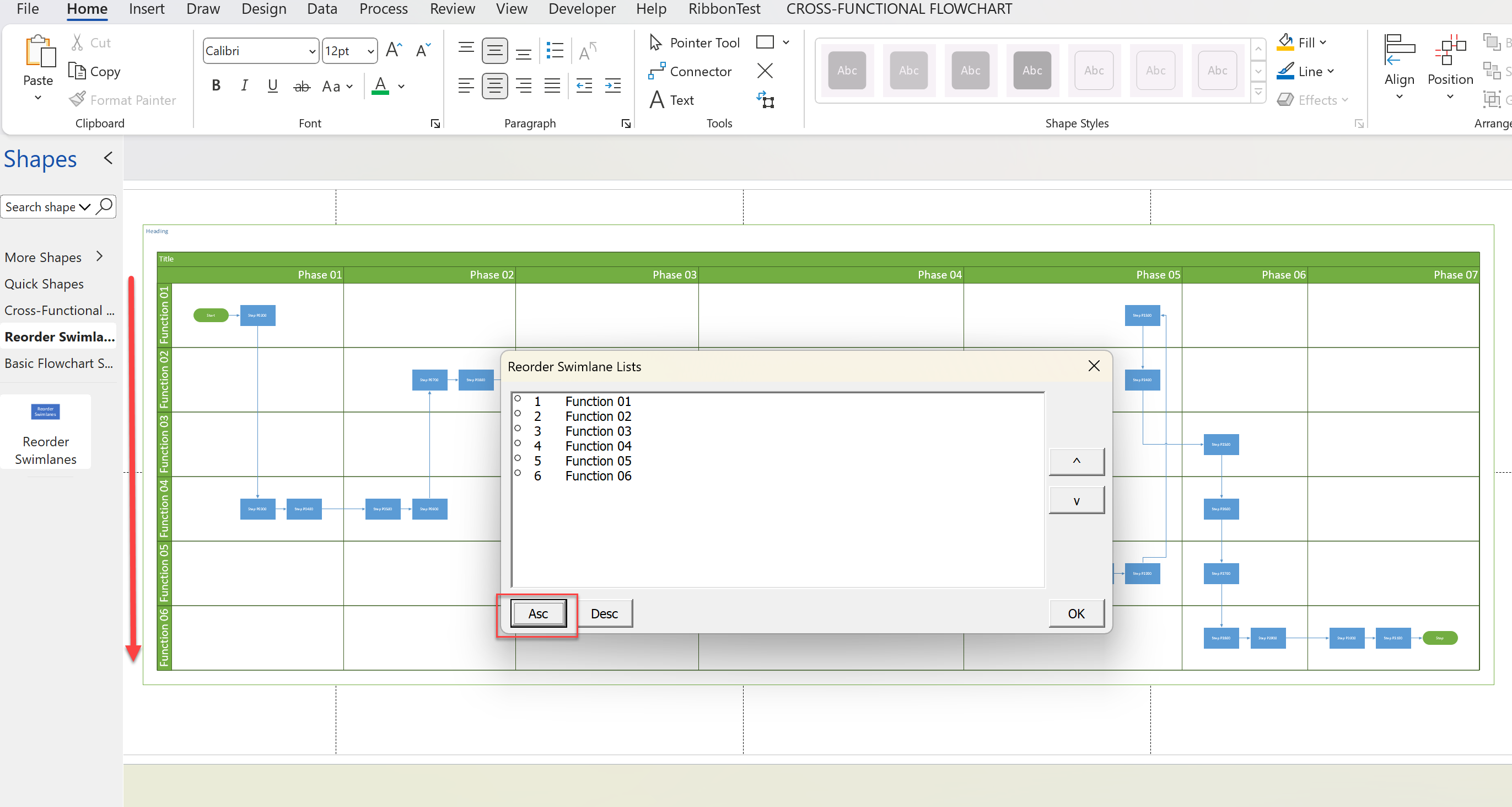
Optimize Visio Flowcharts: Swimlane Reordering Tips
Microsoft Visio desktop Plan 2 and Professional editions provides the ability to create and synchronize cross-functional flowcharts between the diagram and an Excel table. This is great, and widely used for many types of processes. The Excel table normally has a Function / Swimlane column that contains text that becomes labels on the swimlane containers,…
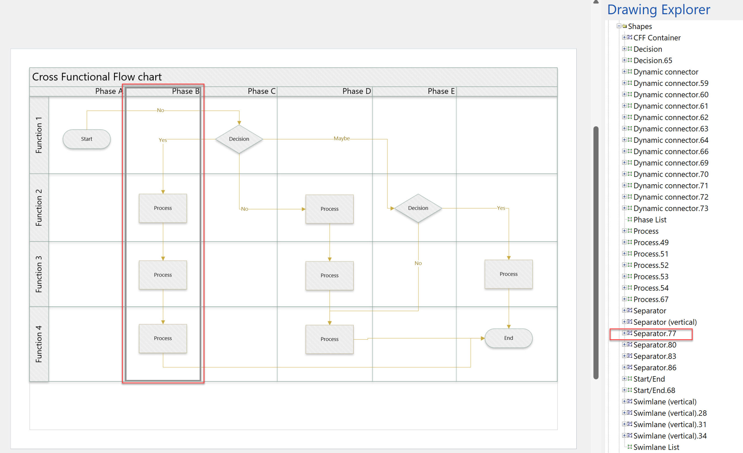
Moving Phases/Separators in Visio Cross-Functional Flowcharts?
I use Visio Cross-Functional Flowcharts a lot, but there is one thing that really bugs me … you can move function bands\swimlanes around, but you can’t move the phases\separators in the same way. The phases/separators are containers just like the function bands\swimlanes, so why can’t I move them? Actually, it is quite understandable when you…
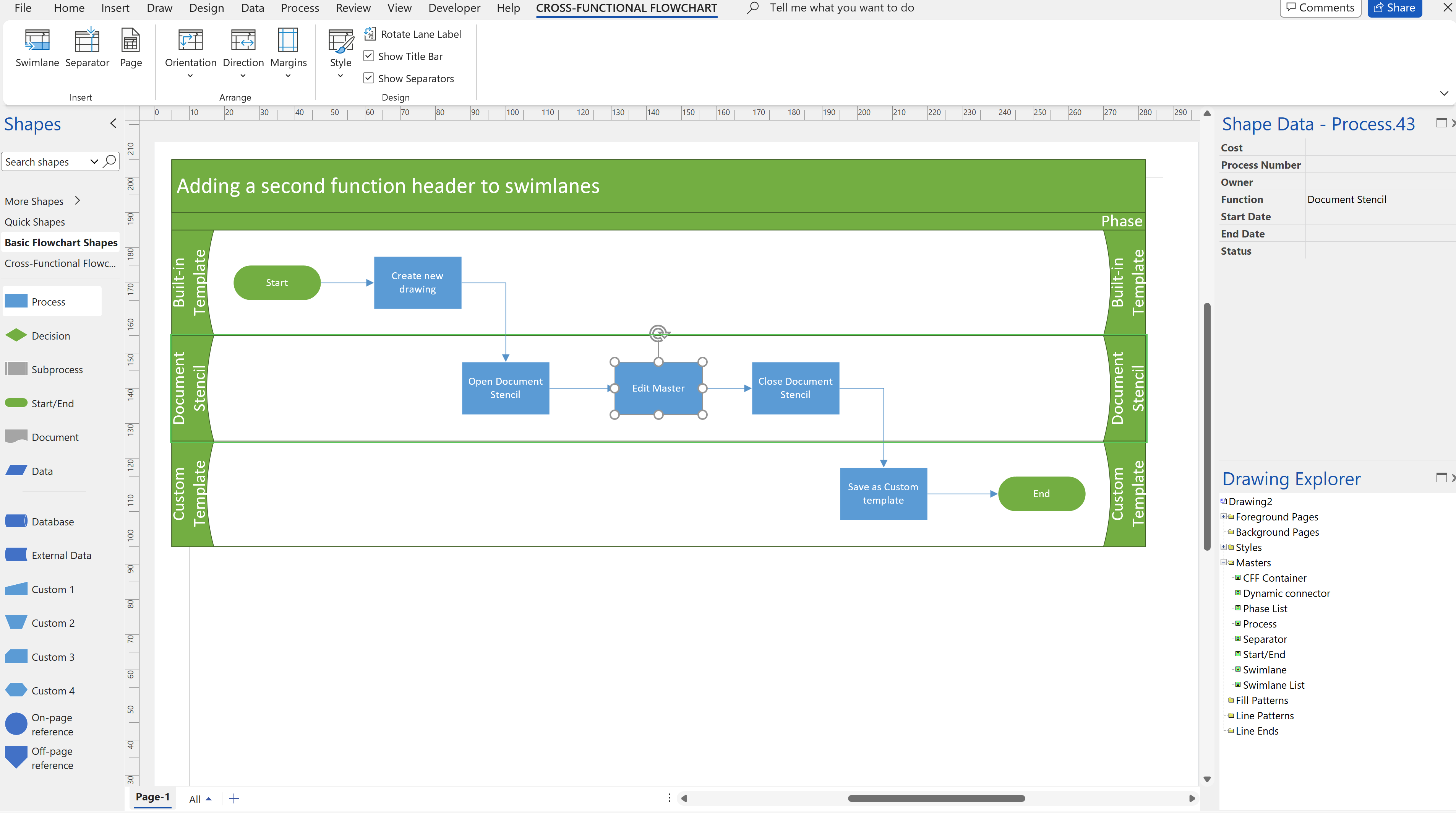
Adding a second Function header bar to Visio swimlanes
I was recently asked if a second function header bar can be added to the swimlanes in the cross-functional flowchart templates in Visio. Some swimlanes can get quite wide, so it can be useful to have a duplicate function header shape on the far-side too. It is quite simple to duplicate the existing function header…
My new book on Visualizing Processes with Microsoft Visio has launched
Back in the early 1990s, there was an application called ABC Flowcharter that was the market leader for diagramming business flowcharts, but some of the brains behind Aldus PageMaker saw an opportunity to create something smarter, and left to write the Visio product, with the stated aim to overtake ABC Flowcharter within 2 years. They…
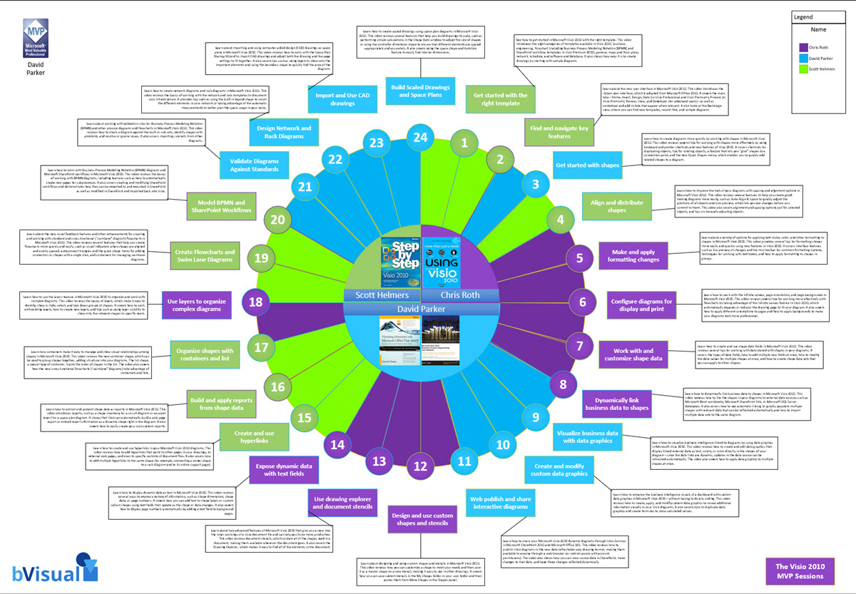
Visio 2010 MVP Session videos reprise
Back in 2012, my fellow Visio MVPs, Scott Helmers and Chris Roth, and I recorded a series of 24 videos about Visio 2010. They were first hosted on Microsoft’s web site, then they put them up on YouTube, they they got deleted :-(. Well, we have managed to retrieve them, and put them back up…
Preventing Deletion of Container Members in Visio
The concept of Structured Diagrams was introduced in Visio 2010 and is featured in many of the templates supplied with Microsoft Visio, and in some third-party solutions, like mine. Connectors, callouts, containers and lists are the key parts of a structured diagrams, and there are times when preventing the deletion of members of a container…
