

When I have reviewed some of the criticisms of connecting shapes in Visio on the web, it has been clear that some users have a misunderstanding about lines and connectors. It is not surprising really because the Microsoft Visio help documentation does not currently make the distinction clear. A connector shape is used to connect two shapes together, whereas a line is normally just a straight line. As usual with Visio though, this is not the whole story because a line can be used to connect two shapes together, and it can be turned into a dynamic connector. I will try to explain myself in this article.
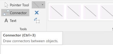
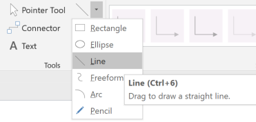
The normal way to connect two shapes together is to use the Connector tool (CTRL+3) on the Home / Tools ribbon, and a line is drawn with the Line (CTRL+6) drop-down menu in the same ribbon group.


Tips and tricks of connectors
The Connector tool (and the Connect Shapes tool) is normally used to connect two shapes together. The connector shape used can be any 1-dimensional master, and there are many examples to be found on the Visio Extras / Connectors stencil.

Note that using a master shape from an stencil will automatically copy the master shape to the local stencil of the active document, if it does not exist there already.
It can be a little confusing that Visio refers to the behavior of connectors as Line on the Developer / Shape Design / Behavior dialog, because a line is not necessarily a connector, as you will read below.

If a connector master is not currently selected in the active stencil, then Visio will automatically use the default Dynamic connector. In fact, if this master does not already exist in the active document, then it is created.

The Dynamic connector master already exists in a number of Microsoft supplied templates because a custom variation of it is required for the type of diagram being drawn.
Tips and tricks about lines
You can use the Line tool to click and drag a new straight line on your Visio page. If you then click elsewhere on the page, you are starting a new line. Each of these lines are perfectly straight, and are known as Line or 1-dimensional (1D) shapes, i.e. they do not have a height.

However, if you were to click and drag from the end point of the line, then you are creating a new segment in the same shape, and the shape changes from having Line (1-dimensional) behavior to having Box (2-dimensional) behavior. You can continue to draw segments, and if you end up exactly back at the start vertex, then the shape can even be filled with a color.

However, usually you miss getting back to the start point exactly but this can be rectified by opening the ShapeSheet and ensuring that the formulas for the final row in the Geometry section points back to the first row. Additionally, the NoFill formula needs to be set to FALSE for any fill colors or patterns to be assigned. Notice how the ShapeSheet 1-D Endpoints section disappear when the shape becomes 2-dimensional!

A line can actually be used to connect two shapes together if the Glue to options on the Snap & Glue settings dialog are changed to allow gluing to shapes.

Another option is to turn a line into a dynamic connector by changing the formula in a single ShapeSheet cell! This magic is done by entering 2 (visLOFlagsRoutable) into the ObjType cell in the Miscellaneous section. This will automatically update the NoAlignBox formula to TRUE, insert the Text Transform section, and add extra connector options to the right-mouse menu. This line now behaves like a dynamic connector shape, and can be used to connector two shapes together without enabling the gluing to shape geometry.

Summary
So, I hope you can see that there is a difference between a line and a connector, and along the way, seen some of the ways that smartness is added to shapes in Visio.