


Microsoft Visio 2010 Premium Edition introduced an extension to the Visio Type Library called the Validation API. This provides the capability to validate a Visio diagram to ensure that its construction complies with industry-standard or company –wide rules.
Organizations are able to use this new feature to encapsulate business logic as validation rules, grouped within rule sets.
Microsoft Visio 2010 Premium edition contains rule sets for use with Basic and Cross-Functional Flowcharts, BPMN Diagrams and SharePoint Workflow Designer diagrams.
This article describes how you can create your own rule sets and rules.
Pre-requisites
This article uses the Validation API that is only found in Microsoft Visio 2010 Premium Edition
It assumes that the reader either has, or has the willingness to get, experience in Visio ShapeSheet formula construction. References are provided at the end of the article.
The rule set development methodology described in this article makes use of VBA macros that are in the downloadable Visio stencil bVisualValidationExplorer.vss
The User Experience
Microsoft Visio 2010 contains an extra tab, Process, in the Fluent UI, which provides access to the visible parts of the Validation API in the Diagram Validation group in the Premium Edition.

The user clicks the Check Diagram button to validate the whole document against the currently enabled rule sets in the document.
Microsoft Visio 2010 and provides several examples of this in use, for example with the new BPMN Diagram and Microsoft SharePoint Workflow templates, and the improvements to the Basic Flowchart and Cross-Functional Flowchart templates, all of which are found in the Flowchart category.
Validating Structured Diagrams
A document can contain multiple rule sets, each of which can be enabled or disabled for the purposes of validating the structure against.
Visio 2010 Premium supports BPMN 1.2, so those organisations that use this particular methodology can verify that diagrams are structured accordingly.

Reviewing Existing Rules
To understand how to create your own rules, it is useful to look at a set of existing rules.
You will need to download the bVisualValidationExplorer.vss linked to from this article, and save it to the MyShapes special folder in our Documents folder.
Open a Basic Flowchart diagram from the Flowchart category.

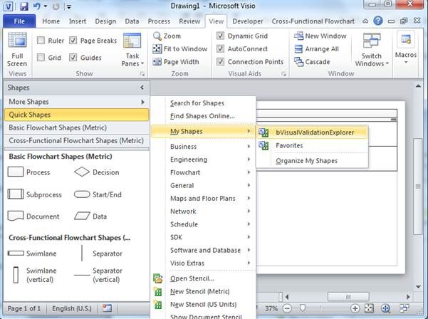
Select More Shapes > My Shapes > bVisualValidationExplorer.
Note : You need to enable macros when prompted.
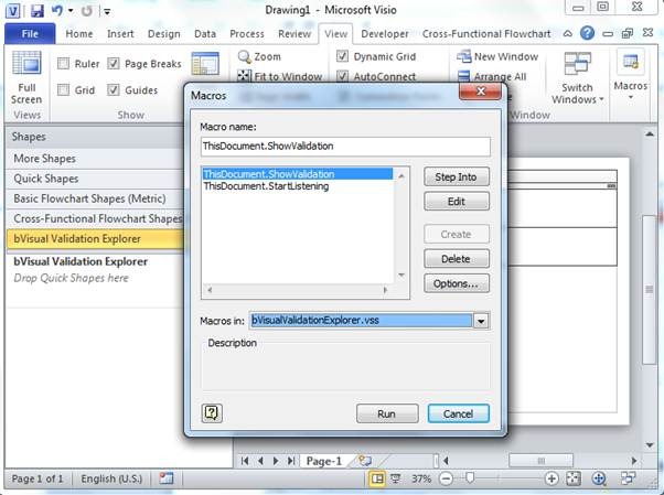
Select View / Macros
Select bVisualValidationExplorer.vss in the Macros in: drop-down list
Select ThisDocument.ShowValidation
Select Run
The bVisual Validation Explorer dialog will open.
Select the Flowchart rule set in the Rule Sets list box.
Select any rule in the Rule list box to review its content
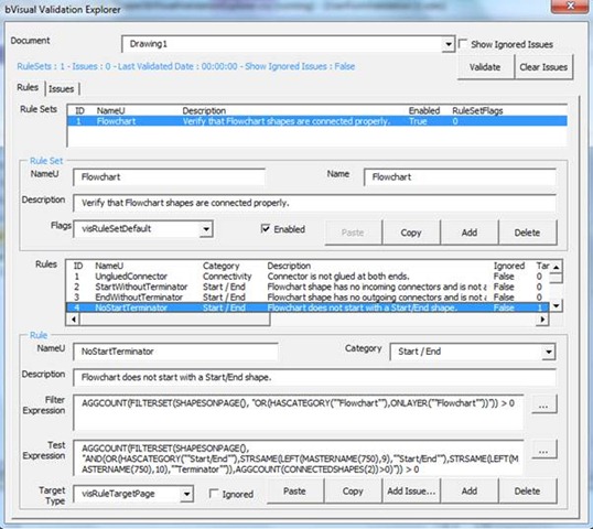
If the text in Filter Expression or Test Expression is too long to see, then click the ellipse (…) button to the right of its text box to open the Property Zoom dialog.
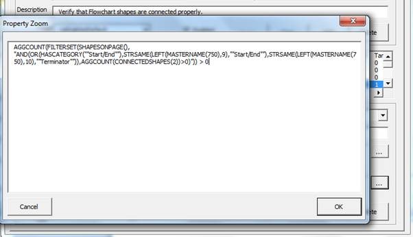
The Filter and Text Expression formulae are normal ShapeSheet functions, apart from a few new special functions added in Visio 2010 especially for Validation.
The following table, which is an extract from the blog The Diagram Validation API (see Reference section), lists the special quasi-ShapeSheet functions that can be used in the Filter and Test Expressions.
| Function | Description |
| Role() | Returns an integer indicating the shape role: {Element = 0, Connector = 1, Container = 2, Callout = 4}. |
| OnLayer(LayerName) | Returns a Boolean indicating whether the shape is a member of the specified layer. Returns a Boolean indicating whether layer exists on page if called on a Page. |
| ConnectedShapes(Direction) | Returns the set of shapes, matching the Direction criteria, connected to the shape. |
| GluedShapes(Direction) | Returns the set of shapes, matching the Direction criteria, glued to the shape. |
| ContainerMembers() | Returns the set of shapes that are members of the container / list shape. |
| ListMembers() | Returns the set of shapes that are members of the list shape. |
| Callouts() | Returns the set of shapes that are callouts on the shape. |
| ParentContainers() | Returns the set of containers that the shape belongs to. |
| ShapesOnPage() | Returns the set of top-level shapes on page. If no page specifier precedes the function, the shape’s containing page is assumed. |
| AggCount(Set) | Counts the number of shapes in a set. |
| FilterSet(Set,FilterExpression) | Returns the subset of shapes in a set that match an expression. |
| OnBoundaryOf() | Returns the set of containers such that the shape is on the boundary of these containers. |
Creating a New Rule Set
Now that we can see how rules are written, we can write some new ones. To show how this can be done, we shall write some simple structured diagramming rules for the Fault Tree Analysis Diagram, which currently has no validation rules attached.
Leave the blank Basic Flowchart drawing open, then create a new Fault Tree Analysis Diagram from the Business category.

You can still run the ShowValidation() macro that is in the bVisualValidationExplorer.vss file because the stencil is docked in the blank Basic Flowchart drawing.
Analyzing the Requirements
The first task is to understand the shapes that are used, or should be used, in the construction of the diagram type. In this case, we will not amend any of the Master shapes because this would make it difficult to retrospectively apply the rules to any previously created diagrams.
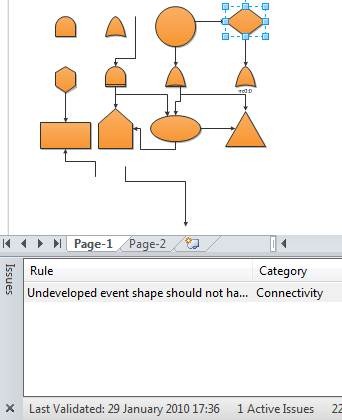
Drag and drop all of the Master shapes from the Fault Tree Analysis Shapes stencil on to the blank page. Then open the Document Stencil and Drawing Explorer window to see what Layers the shapes are on by default. As you can see in the following screenshot, the Dynamic connector is on the Connector layer, and all of the other shapes are on the Flowchart layer.
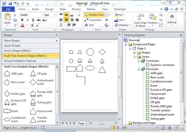
You can also check if the shapes to see if they contain any Shape Data rows. In fact, these particular Master shapes do not.
Next, you can group the masters by usage. In this case there are six Gate symbols; five Event symbols; one Transfer symbol; and one connector.
Now we can start to think about the basic rules that want to create, for example:
1. Every Connector must be connected to a shape at each end
2. Every Event shape must be labelled
3. Every FTA shape must be connected to another FTA shape
4. An Undeveloped Event must not have any outward connections
5. Every Gate shape must have only one input
6. Every Gate, except the Inhibit Gate, must have at least two outputs
7. Inhibit Gate should have one outward connection
8. Every Gate, except the Inhibit Gate, must connect to at least three events
9. A Transfer symbol must have only one connection
In order to create some of these rules, you will need to clarify what a valid shape is.
The first fact we know is that all of the valid shapes are on the Flowchart layer. You can use the OnLayer(LayerName) function for this.
The second fact we know is the names of the Master shapes. You can use the MasterName(langid_opt) function for this, but you need to exercise a little caution because . This is because it is easy for a user to accidently create duplicate Masters in a document, in which case Visio will automatically force the duplicate master name to be unique be appending a dot and a number. Consequently, you should modify the test to be StrSame(Left(MasterName(750),n),Name), where 750 is the universal language code, and Name is the name of the Master to be checked, and n is the number of characters in the Name.
In the flowchart templates that already have rules supplied; the Master shapes have been modified to include an extra user-defined cell, User.msvShapeCategories, which can contain a list of categories that the shape belongs to. The new function, HasCategory(CategoryName), can then be used as a test rather than the MasterName() function. If you are creating your own template with local copies of the masters, then you do have the option of adding the User.msvShapeCategories to your copy of the masters. If you do create your own versions of the masters, then be sure to tick the Match master by name on drop property of each Master . This will ensure that your modified master is used, rather than the original one.
Adding a Rule Set
First, you must create a rule set for the rules to belong to.
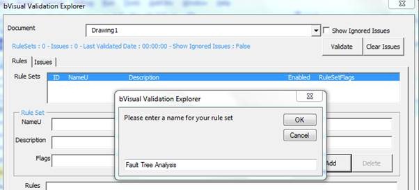
Run the macro ShowValidation() to open the bVisual Validation Explorer dialog.
Select Add then enter a name for the rule set, eg Fault Tree Analysis
You can then edit the localized Name, and Description of the new rule set.
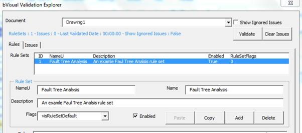
You are now ready to add rules.
Every Connector must be connected to a shape at each end
The Flowchart rule set in the Basic Flowchart drawing already has such a rule, therefore you can copy this one from there.
Select the blank Basic Flowchart drawing from the Document drop-down list (in this case it is called Drawing3)
The Flowchart rule set will be displayed in the Rule Sets list box
Select the UngluedConnector rule in the Rules list box
Select the Copy button below the Test Expression list box. This will create a temporary copy of the rule.
Select your blank Fault Tree Analysis drawing in the Document pull down list in this case called Drawing1).
Ensue that your new rule set, Fault Tree Analysis, is selected.
Select the Paste button on below the Test Expression text box.
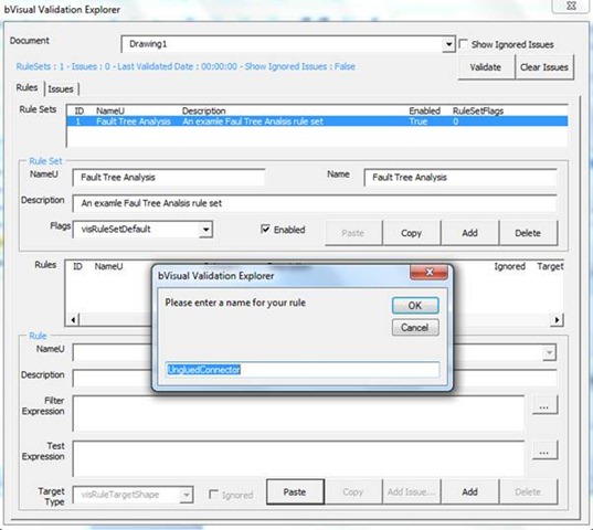
You can accept the default name offered, or enter a new one.
When you select OK, the rule is pasted into the selected rule set.
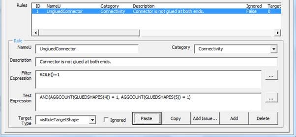
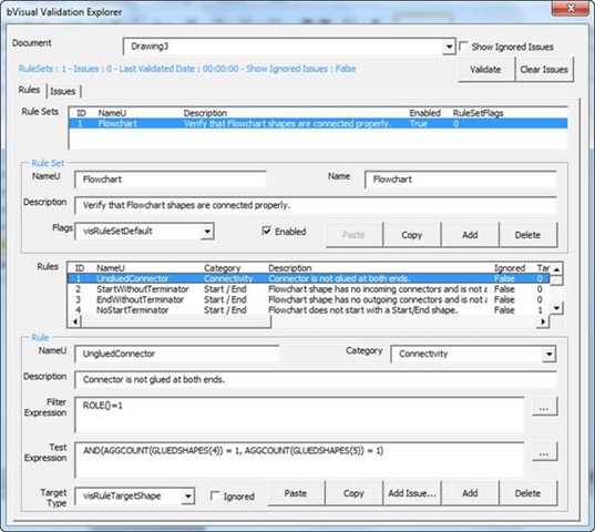
The NameU is the unique identifier of this particular rule in the rule set, but it will not appear in the Issues Window.
The Category can be any text value you want to describe the group that this belongs to. It will be displayed in the Issues Window.
The Description will also appear in the Issues Window.
The Filter Expression, Role()=1, means that only connector (1D) shapes are to be tested.
The Test Expression, AND(AGGCOUNT(GLUEDSHAPES(4)) = 1, AGGCOUNT(GLUEDSHAPES(5)) = 1), can be broken down into:
GluedShapes(n), where n is one of the following Visio.VisGluedShapesFlags constant values:
· visGluedShapesAll1D = 0
· visGluedShapesIncoming1D = 1
· visGluedShapesOutgoing1D = 2
· visGluedShapesAll2D = 3
· visGluedShapesIncoming2D = 4
· visGluedShapesOutgoing2D = 5
AggCount(…) returns the count of items found.
Thus the whole formula checks that there is a 2D shape connected to the start of the connector, and a 2D shape connected to the end of the connector.
The Target Type for this rule (and all of the others in this article) is the default visRuleTargetShape
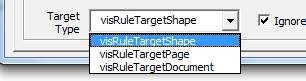
The Visio.VisRuleTargets constant values are:
· visRuleTargetShape = 0
· visRuleTargetPage = 1
· visRuleTargetDocument = 2
You can then place down a few connectors, connected in various ways, in order to verify the correctness of your rule.
Then select the Check Diagram button in the Diagram Validation group on the Process tab to see if the rule is working correctly.
TIP : Apply a theme to the document that includes arrowheads for the connectors, because you can then spot the start and end of it!

Every Event shape must be labelled
There is also a rule called NoShapeText in the Flowchart rule set in your blank Basic Flowchart drawing.
Repeat the actions described above to copy this rule set too.

The Filter Expression needs to be modified though, because the FTA shapes do not contain the categories user-defined cell. Therefore, you have to check for the master names specifically instead of using the HasCategory() function.
AND(ONLAYER(“Flowchart”),OR(STRSAME(LEFT(MASTERNAME(750),11),”Basic event”),STRSAME(LEFT(MASTERNAME(750),17),”Undeveloped event”),STRSAME(LEFT(MASTERNAME(750),5),”Event”),STRSAME(LEFT(MASTERNAME(750),11),”House event”),STRSAME(LEFT(MASTERNAME(750),17),”Conditional event”)))
The Test Expression, NOT(STRSAME(SHAPETEXT(TheText), “”)), simply tests that there is any text in the shape.
To check that this rule is working, you can mark the first rule, UngluedConnector, as Ignored at the bottom of the dialog.

Then select the Issues tab on the bVisual Validation Explorer dialog.
Select the Validate button.
Your document, which contains one copy of each shape, and a few connectors, will be validated.
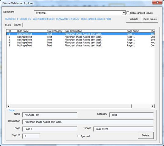
The Show Ignored Issues check box at the top of this dialog performs the same action as the same named item in the right mouse menu of the Issues Window.
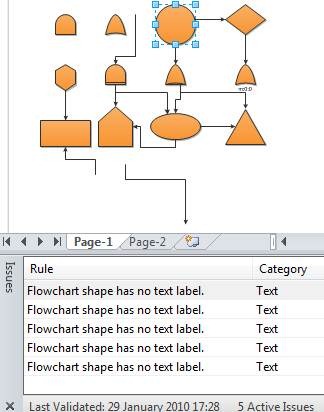
You should select each row in the Issues Window to test that the shape has been correctly found by the rule.
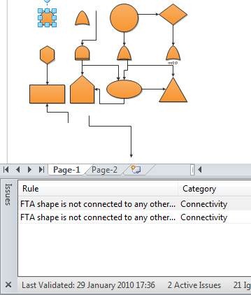
Every FTA shape must be connected to another FTA shape
Like the first two examples, you can copy the rule UnconnectedShape from the blank Basic Flowchart document.
You can change the Description to read FTA shape is not connected to any other shape.
Like the NoShapeText rule, you need to amend the Filter Expression to read ONLAYER(“Flowchart”)
You could possibly expand this rule to be more prescriptive about the actual names of the Master shapes that are connected.
Similar to before, you can mark the previous rules as Ignored before validating the drawing.
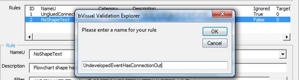
An Undeveloped Event must not have any outward connections
You have now run out of rules to copy, so you will have select the Add button at the bottom of the dialog.
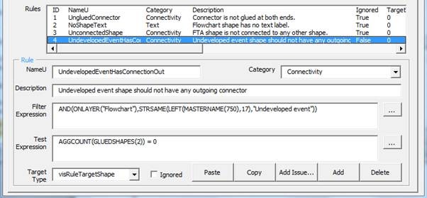
Enter the name UndevelopedEventHasConnectionOut
Enter, or select from the drop-down list, the Category : Connectivity
Enter the Description : Undeveloped event shape should not have any outgoing connector
Enter the Filter Expression : AND(ONLAYER(“Flowchart”),STRSAME(LEFT(MASTERNAME(750),17),”Undeveloped event”))
Enter the Test Expression : AGGCOUNT(GLUEDSHAPES(2)) = 0
You should now test your rule by connecting and disconnecting an Undeveloped event shape, and selecting the Check Diagram button in between.
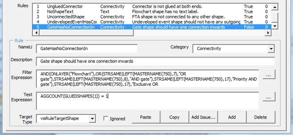
Every Gate shape must have only one input
Select the Add button at the bottom of the dialog.
Enter the NameU : GateHasNoConnectionIn
Enter, or select from the drop-down list, the Category : Connectivity
Enter the Description : Gate shape should have one connection inwards
Enter the Filter Expression : AND(ONLAYER(“Flowchart”),OR(STRSAME(LEFT(MASTERNAME(750),7),”OR gate”),STRSAME(LEFT(MASTERNAME(750),8),”AND gate”),STRSAME(LEFT(MASTERNAME(750),17),”Priority AND gate”),STRSAME(LEFT(MASTERNAME(750),17),”Exclusive OR gate”),STRSAME(LEFT(MASTERNAME(750),11),”Voting gate”),STRSAME(LEFT(MASTERNAME(750),12),”Inhibit gate”)))
Enter the Test Expression : AGGCOUNT(GLUEDSHAPES(1)) = 1
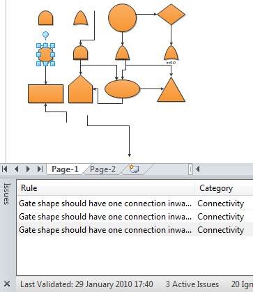
You should now test your rule by connecting and disconnecting your gate shapes, and selecting the Check Diagram button in between.
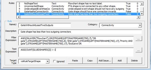
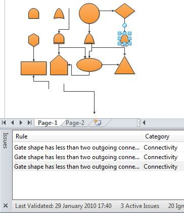
Every Gate, except the Inhibit Gate, must have at least two outputs
Select the Add button at the bottom of the dialog.
Enter the NameU : GateWithoutAtLeastTwoOutputs
Enter, or select from the drop-down list, the Category : Connectivity
Enter the Description : Gate shape has less than two outgoing connectors
Enter the Filter Expression : AND(ONLAYER(“Flowchart”),OR(STRSAME(LEFT(MASTERNAME(750),7),”OR gate”),STRSAME(LEFT(MASTERNAME(750),8),”AND gate”),STRSAME(LEFT(MASTERNAME(750),17),”Priority AND gate”),STRSAME(LEFT(MASTERNAME(750),17),”Exclusive OR gate”),STRSAME(LEFT(MASTERNAME(750),11),”Voting gate”)))
Enter the Test Expression : AGGCOUNT(GLUEDSHAPES(2)) > 1
You should now test your rule by connecting and disconnecting your gate shapes, and selecting the Check Diagram button in between.
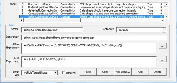
Inhibit Gate should have one outward connection
Select the Add button at the bottom of the dialog.
Enter the NameU : InhibitGateNeedsOneOutput
Enter, or select from the drop-down list, the Category : Connectivity
Enter the Description : Inhibit Gate shape should have only one outgoing connector
Enter the Filter Expression : AND(ONLAYER(“Flowchart”),STRSAME(LEFT(MASTERNAME(750),12),”Inhibit gate”))
Enter the Test Expression : AGGCOUNT(GLUEDSHAPES(2)) = 1
You should now test your rule by connecting and disconnecting your Inhibit gate shapes, and selecting the Check Diagram button in between.

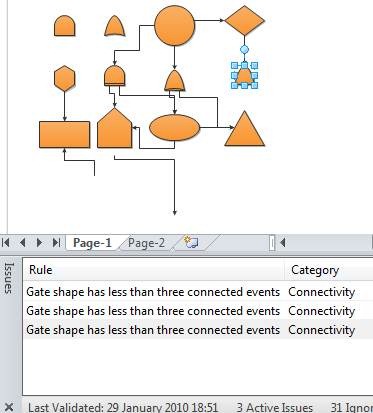
A Gate, except the Inhibit gate, must be connected to at least three events
Select the Add button at the bottom of the dialog.
Enter the NameU : GateMustConnectAtLeastThreeEvents
Enter, or select from the drop-down list, the Category : Connectivity
Enter the Description : Gate shape has less than three connected events
Enter the Filter Expression : AND(ONLAYER(“Flowchart”),OR(STRSAME(LEFT(MASTERNAME(750),7),”OR gate”),STRSAME(LEFT(MASTERNAME(750),8),”AND gate”),STRSAME(LEFT(MASTERNAME(750),17),”Priority AND gate”),STRSAME(LEFT(MASTERNAME(750),17),”Exclusive OR gate”),STRSAME(LEFT(MASTERNAME(750),11),”Voting gate”)))
Enter the Test Expression : AGGCOUNT(FILTERSET(CONNECTEDSHAPES(0),ONLAYER(“Flowchart”))) = 3
The Visio.VisConnectedShapesFlags constant values are:
· visConnectedShapesAllNodes = 0
· visConnectedShapesIncomingNodes = 1
· visConnectedShapesOutgoingNodes = 2

You should now test your rule by connecting and disconnecting your gate shapes, and selecting the Check Diagram button in between.
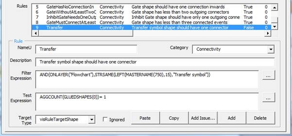
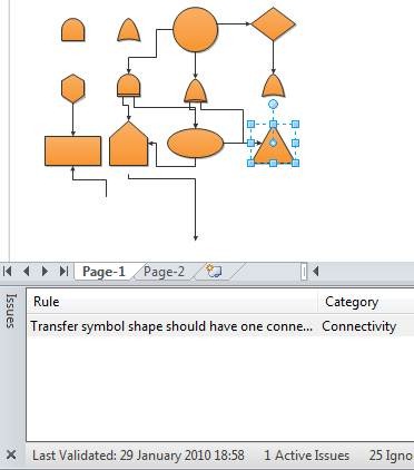
A Transfer symbol must have only one connection
Select the Add button at the bottom of the dialog.
Enter the NameU : TransferSymbolNeedsOneConnection
Enter, or select from the drop-down list, the Category : Connectivity
Enter the Description : Transfer symbol shape should have one connector
Enter the Filter Expression : AND(ONLAYER(“Flowchart”),STRSAME(LEFT(MASTERNAME(750),15),”Transfer symbol”))
Enter the Test Expression : AGGCOUNT(GLUEDSHAPES(0))= 1
You should now test your rule by connecting and disconnecting your Transfer symbol shapes, and selecting the Check Diagram button in between.
Publishing Rules
Rule sets are saved in Visio documents, so you can save your blank FTA document as, say, Fault Tree Validation Rules.vsd. You could save it as a template too. In either case, if you base a drawing on it, then it will contain your rule set.
Alternatively, you could import the rule set into an existing or new drawing using the Check Diagram /Import Rules From action:
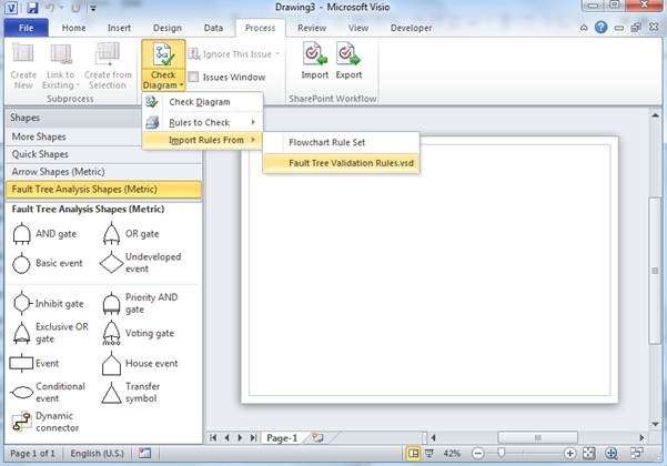
Of course, you will need to open the drawing first.
References
A few relevant online articles are listed below.
Visio Insight blogs
bVisual Blogs
| Title | Link |
| Visio 2010 Validation Rules (part 1) | Visio 2010 Validation Riles (Part 1) |
| Visio 2010 Validation Rules (part 2) | Visio 2010 Validation Rules (part 2) |
| Visio 2010 : Containment and Cross-Functional Flowcharts | Visio 2010 : Containment and Cross-Functional Flowcharts |
I am currently working on a new book about the validation rules in Visio 2010 for Packt Publishing which will be published soon.