

A couple of posts in the Visio newsgroups got me thinking this weekend. One was from an Autocad conversant user who would prefer Visio to draw a continuous line between points rather than doing the normal click, hold and drag with line tool because he has tendonitis; and the other wanted to draw a circle centered on a vertex because he is drawing land boundaries.
Visio has a PolyLine line type, but, as far as I am aware, it can only be created in code – there is no menu or toolbar button to enable you to use it. It was introduced for converting CAD lines, and is simply a series of X and Y co-ordinates in a single cell, rather than the normal co-ordinate per row.
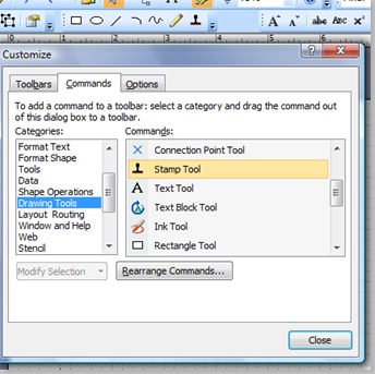
Visio has a Stamp Tool, which used to be on a toolbar out-of-the-box, but it seems to have disappeared in Office Visio 2007. Fortunately, it is simple to put it back by selecting Add or Remove Buttons / Customize from the down arrow at the end of any of the toolbars. This will open the Customize dialog, and then you can navigate to the Drawing Tools category, and scroll down to Stamp Tool. You can then click and drag it onto any toolbar, such as the Drawing toolbar in the example below.

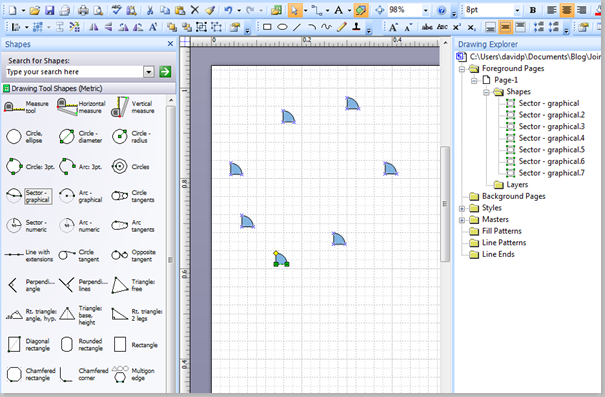
The Stamp Tool enables you to drop a master shape instance with each click of the mouse. For example, I have selected the Sector – graphical master from the Visio Extras / Drawing Tool Shapes stencil, then I have selected the Stamp Tool and clicked seven times in the page.

To stop the Stamp Tool, simply Pointer Tool on the Standard toolbar.
I have included the CreatePolyLine VBA macro in this post, which has a boolean argument to optionally delete the existing shapes. To run the macro, simply select the first shape in the sequence that you want to trace a line between. I have assumed that you would put down a sequence of shapes, then select my macro immediately after re-selecting the first shape in the sequence. Then I selected my macro DrawPolyLineBetween to draw a line between each of the
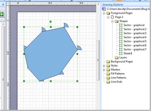

The Sector – graphical shapes can be modified to snap to the geometry of the new polyline shape, if desired.

Alternatively, you can run the DrawReplacementPolyLine macro to create a polyline shape that automatically deletes the original shapes.
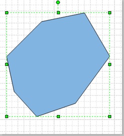

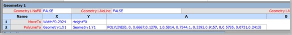
The new polyline shape has a single geometry section in the ShapeSheet, which uses the PolyLineTo row type, as follows:

In the following code, I have tested the vertex shapes to see if they are 1D or not. If they are 1D, then I have used the BeginX and BeginY co-ordinates as the vertex position, but if they are not 1D, then I have use the PinX and PinY co-ordinates. I have assumed that you are trying to create a closed shape – that is one where the line returns to where it started from.
Option Explicit
Public Sub DrawPolyLineBetween()
CreatePolyLine False
End Sub

Public Sub DrawReplacementPolyLine()
CreatePolyLine True
End Sub

Private Sub CreatePolyLine(ByVal deleteOriginalShapes As Boolean)
'Author: David J Parker, bVisual - Dec 2007
'Usage : Draw a poly line between existing shapes
'Params: Optionally delete existing shapes
If Visio.ActiveWindow.Selection.Count = 0 Then
'Nothing selected
Exit Sub
End If
Dim pag As Visio.Page
Dim shp As Visio.Shape

Set shp = Visio.ActiveWindow.Selection.PrimaryItem
Set pag = Visio.ActivePage

If pag.Shapes.Count = shp.Index Then
'No subsequent shapes to loop thru
Exit Sub
End If
Dim shpIndex As Integer
Dim vertexShape As Visio.Shape
Dim lineShape As Visio.Shape
Dim vertices As Integer
Dim xyArray() As Double

For shpIndex = shp.Index To pag.Shapes.Count
Set vertexShape = pag.Shapes(shpIndex)
vertices = vertices + 1
setVertices xyArray(), vertexShape, vertices
Next shpIndex

'Close the line
Set vertexShape = pag.Shapes(shp.Index)
vertices = vertices + 1
setVertices xyArray(), vertexShape, vertices
Set lineShape = pag.DrawPolyline(xyArray(), 0)
If deleteOriginalShapes = True Then
For shpIndex = pag.Shapes.Count - 1 To shp.Index Step -1
pag.Shapes(shpIndex).Delete
Next shpIndex
End If
End Sub

Private Sub setVertices(ByRef xyArray() As Double, _
ByVal vertexShape As Visio.Shape, ByVal vertices As Integer)
ReDim Preserve xyArray((2 * vertices) - 1)
If vertexShape.OneD = 0 Then
xyArray((2 * vertices) - 2) = vertexShape.CellsSRC( _
Visio.VisSectionIndices.visSectionObject, _
Visio.VisRowIndices.visRowXFormOut, _
Visio.visXFormPinX).ResultIU
xyArray((2 * vertices) - 1) = vertexShape.CellsSRC( _
Visio.VisSectionIndices.visSectionObject, _
Visio.VisRowIndices.visRowXFormOut, _
Visio.visXFormPinY).ResultIU
Else
xyArray((2 * vertices) - 2) = vertexShape.CellsSRC( _
Visio.VisSectionIndices.visSectionObject, _
Visio.VisRowIndices.visRowXForm1D, _
Visio.vis1DBeginX).ResultIU
xyArray((2 * vertices) - 1) = vertexShape.CellsSRC( _
Visio.VisSectionIndices.visSectionObject, _
Visio.VisRowIndices.visRowXForm1D, _
Visio.vis1DBeginY).ResultIU
End If
End Sub
Note to Microsoft Visio team:-
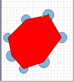
In preparation for this blog entry, I noticed that the Stamp Tool has a bug, or at least it behaves differently from normal usage. – if the page is scaled then the stamped master instances are scaled, but the same master, when dragged from the stencil, are sometimes not. Thus the two operations do not produce a shape of the same size:-
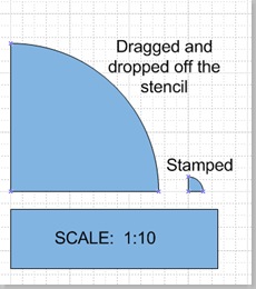

In my limited testing, this behavior is limited to more complex 1D masters.